Sulfur-iron autotrophic denitrification device and application thereof

A technology of autotrophic denitrification and iron sulphur, applied in chemical instruments and methods, water pollutants, water/sludge/sewage treatment, etc., can solve the problems of large floor space, increased operating costs, and unfavorable removal of nitrogen and phosphorus. , to achieve the effect of saving operating costs, saving floor space, and avoiding hardening and replacement problems

Pending Publication Date: 2019-12-27
JIANGNAN UNIV
View PDF5 Cites 5 Cited by
  • Summary
  • Abstract
  • Description
  • Claims
  • Application Information

AI Technical Summary

Problems solved by technology

In order to achieve the standard discharge of effluent, most sewage treatment plants need to ensure sufficient hydraulic retention time in the biochemical tank. The hydraulic retention time of anaerobic, anoxic and aerobic sections is generally not less than 1h, 3h and 8h respectively, and is To realize the deep removal of nitrogen and phosphorus, the effluent of the biochemical tank generally needs to be equipped with a denitrification filter for deep denitrification, coagulation sedimentation filtration or air flotation process to achieve deep phosphorus removal, resulting in a long sewage treatment process and a large area. Moreover, the dosage of carbon sources and phosphorus removal agents is relatively large, which increases operating costs and is not conducive to low-carbon emissions and circular economy development models
In the prior art, iron filings and sulfur are usually directly formed into a mixed layer, which tends to harden the iron filings and sulfur particles, resulting in short flow, which is not conducive to the removal of nitrogen and phosphorus.

Method used


Image

  • Sulfur-iron autotrophic denitrification device and application thereof
  • Sulfur-iron autotrophic denitrification device and application thereof
  • Sulfur-iron autotrophic denitrification device and application thereof

Examples


Embodiment 1

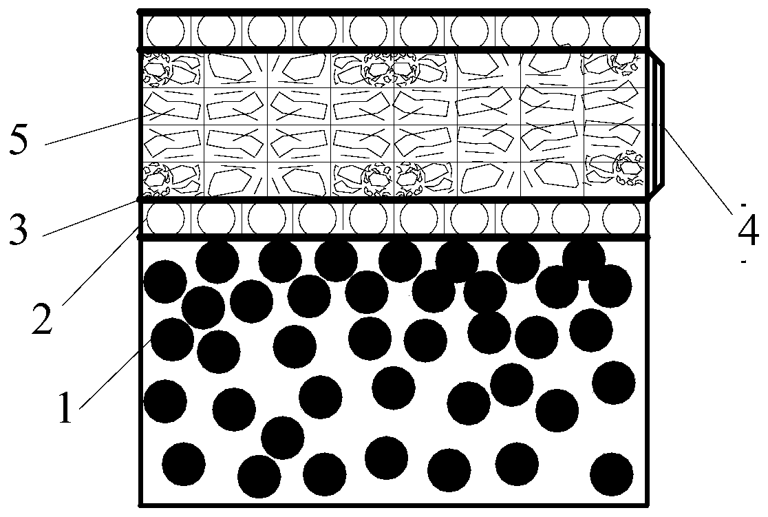
[0043] Embodiment 1: iron sulfur filler layer

[0044] The structure of the sulfur iron filler is as figure 1 As shown, the sulfur iron packing layer includes sulfur particles 1 and an iron packing layer, and the iron packing layer is provided with a supporting layer 3 up and down, and a screen is arranged in the middle, and a water distribution hole 2 is provided in the supporting layer; In the iron filler layer, iron filings 5 ​​are placed in the screen, and iron filler replacement openings 4 are provided on the side of the iron filler layer. The iron filings 5 ​​are placed in the screen and arranged in a multi-stage sulfur-iron arrangement, which is conducive to giving full play to the effect of iron chemical phosphorus removal, and when the iron filings are consumed and cannot meet the requirements of phosphorus removal, they can be carried out through the replacement opening The replacement of iron packing is convenient and quick, which effectively avoids the problems of...

Embodiment 2

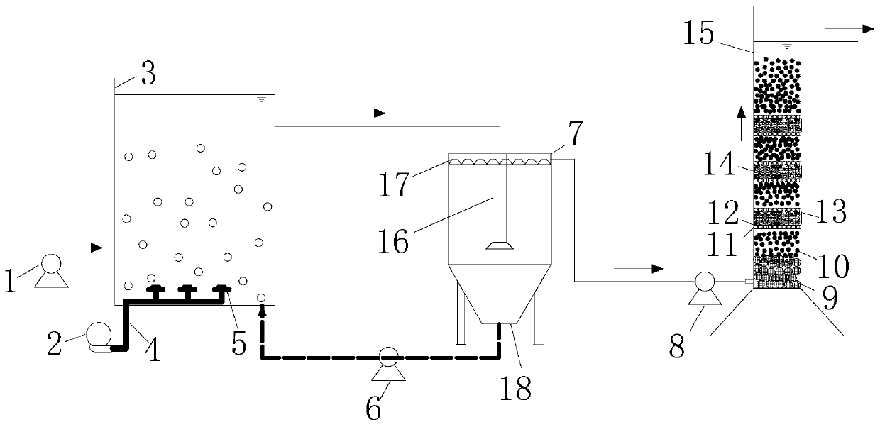
[0045] Embodiment 2: CAS / S-Fe autotrophic denitrification process

[0046] Such as figure 2 As shown, the reactor is made of acrylic plate, and the combined process includes an aeration tank 3, a sedimentation tank 7 and a sulfur iron autotrophic denitrification filter 15; the aeration tank 3 includes a water inlet, a water outlet and an aeration device; the water inlet is located at the lower part of the aeration tank, and is connected with the water inlet pump 1; The outside of the air tank 3 is connected to the aerator 5 through the aeration pipe 4 .

[0047] The sedimentation tank 7 is in an inverted cone shape, and the sedimentation tank 7 includes a diversion pipe 16, an outlet weir 17 and a mud collection bucket 18; The water outlets are connected; the outlet weir 17 is located at the top of the sedimentation tank 7; the mud collecting bucket 18 is located at the bottom of the sedimentation tank 7; connected; the sedimentation tank 7 is connected with the sulfur iro...

Embodiment 3

[0053] Embodiment 3: MBR / S-Fe autotrophic denitrification process

[0054] Such as Figure 8 As shown, the material of the reactor is an acrylic plate, the combined process includes an MBR pool 7 and an S-Fe filter tank 15, the effective volumes are respectively: 15L and 6L, and the MBR / S-Fe autotrophic denitrification device is sequentially equipped with MBR Pond 7 and sulfur-iron autotrophic denitrification filter 15; Described sulfur-iron autotrophic denitrification filter 15 is connected with MBR outlet pipe 6 by MBR outlet water pump 8; Described sulfur-iron autotrophic denitrification filter 15 is provided with packing layer , the packing layer includes stone grains 9 and iron sulfur packing layer from bottom to top; the sulfur iron packing layer includes sulfur particles 10 and iron packing layer, and the iron packing layer is provided with a support layer 12 up and down, and a screen is set in the middle, Water distribution holes 11 are provided in the support layer 1...


PUM

PropertyMeasurementUnit
particle diameteraaaaaaaaaa
pore sizeaaaaaaaaaa
diameteraaaaaaaaaa

Abstract

The invention discloses a sulfur-iron autotrophic denitrification device and application thereof, and belongs to the technical field of sewage treatment. According to the discontinuously-arranged structure-replaceable ferro-sulfur filler, a ferro-sulfur filler layer comprises sulfur particles and an iron filler layer, supporting layers are arranged on the upper portion and the lower portion of theiron filler layer, a screen is arranged in the middle of the iron filler layer, and water distribution holes are formed in the supporting layers; the iron filler layer is formed by placing scrap ironin the screen, and an iron filler replacement opening is further formed in the side face of the iron packing layer. Scrap iron is placed in the screen and arranged in a multi-stage sulfur-iron arrangement mode, the effect of iron chemical phosphorus removal can be brought into full play, when the scrap iron is consumed and cannot meet the phosphorus removal requirement, the iron filler can be replaced through the replacement opening, convenience and quickness are achieved, and the problems of hardening and replacement of the filler are effectively avoided. And stone particles are added into the sulfur packing layer to uniformly distribute water.

Description

technical field [0001] The invention relates to a sulfur-iron autotrophic denitrification device and its application, belonging to the technical field of sewage treatment. Background technique [0002] At present, domestic urban sewage treatment plants have generally implemented the first-level A discharge standard (hereinafter referred to as "first-level A standard") in the "Pollutant Discharge Standards for Urban Sewage Treatment Plants" (GB18918-2002), and the effluent COD, total nitrogen, ammonia nitrogen, The indicators of major pollutants such as total phosphorus shall not exceed 50mg / L, 15mg / L, 5mg / L, and 0.5mg / L respectively. On June 1, 2018, the "Discharge Limits of Main Water Pollutants of Urban Sewage Treatment Plants and Key Industries in Taihu Lake Area" (DB 32 / 1072-2018) was promulgated and implemented, requiring urban sewage treatment plants in Taihu Lake area of ​​Jiangsu Province to be at Grade A Standards were raised on the basis of standards, among which ...

Claims


Application Information

Patent Timeline
Patent Type & Authority Applications(China)
IPC IPC(8): C02F3/30C02F101/10C02F101/16
CPCC02F3/302C02F2101/105C02F2101/16
Inventor 李激郑凯凯王燕吕金泽王硕王小飞杨童王水兵
Owner JIANGNAN UNIV
Why Eureka
Try Eureka