Crystal bar workpiece plate, and crystal bar cutting device and cutting method

A cutting method and cutting device technology, applied to fine working devices, working accessories, manufacturing tools, etc., can solve problems such as time-consuming and labor-intensive damage to crystal rods, and achieve the effects of convenient use, improved quality, and reduced labor costs

Inactive Publication Date: 2019-12-31
ZING SEMICON CORP
View PDF6 Cites 3 Cited by
  • Summary
  • Abstract
  • Description
  • Claims
  • Application Information

AI Technical Summary

Problems solved by technology

[0003] In view of the above-mentioned shortcomings of the prior art, the object of the present invention is to provide a crystal ingot workpiece plate, a crystal ingot cutting device and a cutting method, which are used to solve the problem of failure in the prior art when the crystal orientation re-inspection of the crystal ingot fails. It needs to be degummed and then re-coated, and the degumming process is not only time-consuming and labor-intensive, but also easily leads to problems such as crystal rod damage

Method used


Image

  • Crystal bar workpiece plate, and crystal bar cutting device and cutting method
  • Crystal bar workpiece plate, and crystal bar cutting device and cutting method
  • Crystal bar workpiece plate, and crystal bar cutting device and cutting method

Examples


Embodiment 1

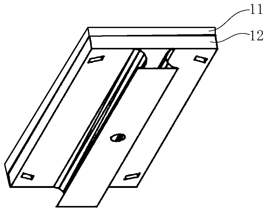
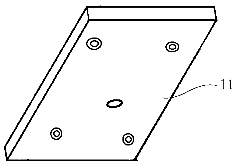
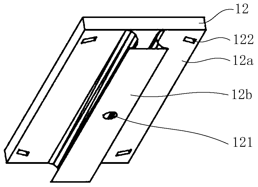
[0039] Such as Figure 1 to Figure 4 As shown, the present invention provides a crystal ingot workpiece plate, comprising: a fixed plate 11 and an adjustment plate 12, the fixed plate 11 is used to place crystal ingots; the adjustment plate 12 is located on the fixed plate 11 away from the ingot The surface of the adjustment plate 12 is provided with a center hole 121 and several waist-shaped through holes 122, the center hole 121 is located in the middle of the adjustment plate 12, and the several waist-shaped through holes 122 are located at the center of the circle The periphery of the hole 121; the fixed plate 11 and the adjustment plate 12 are connected by bolts located in the center hole 121 and the several waist-shaped through holes 122, and the bolts located in the waist-shaped through holes 122 It can be moved in the waist-shaped through hole 122 to adjust the relative positions of the fixing plate 11 and the adjusting plate 12, so as to realize the adjustment of the ...

Embodiment 2

[0049] Such as Figure 5 As shown, the present invention also provides a crystal rod cutting device, comprising:

[0050] Ingot workpiece plate as described in embodiment one;

[0051] The carrying platform 3, the ingot 2 to be cut is placed on the carrying platform 3 through the ingot workpiece plate;

[0052] A cutting unit 4, the cutting unit 4 is located above the crystal ingot 2 during non-cutting operation;

[0053] The detection unit 5 is located above the crystal ingot 2 and is used for detecting the off-angle of the crystal ingot 2 .

[0054] For the introduction of the crystal ingot workpiece plate, please refer to Embodiment 1, and details are not repeated for the purpose of brevity.

[0055] The specific structure of the carrying platform 3 can be adjusted according to the specific structure of the adjusting plate 12. For example, in this embodiment, the carrying platform 3 can be provided with a recess corresponding to the boss portion 12b of the adjusting plat...


PUM

PropertyMeasurementUnit
angleaaaaaaaaaa

Abstract

The invention provides a crystal bar workpiece plate, and a crystal bar cutting device and method. The crystal bar workpiece plate comprises a fixed plate and an adjustment plate, wherein the fixed plate is used for placing a crystal bar; the adjustment plate is located on a surface away from the crystal bar, of the fixed plate, a circle center hole and a plurality of waist-shaped through holes are formed in the adjustment plate, the circle center hole is located in the middle of the adjustment plate, and the plurality of waist-shaped through holes are located in the periphery of the circle center hole; and the fixed plate is connected with the adjustment plate through bolts located in the circle center hole and the plurality of waist-shaped through holes, and the bolts in the waist-shapedthrough holes are capable of moving in the waist-shaped through holes to adjust the relative positions of the fixed plate and the adjustment plate, so that adjustment for a crystal orientation deflection angle of the crystal bar is realized. According to the crystal bar workpiece plate, and the crystal bar cutting device and method, position adjustment for the crystal bar is realized through thestructural design that the fixed plate and the adjustment plate are cooperated, and by adjusting the position of the adjustment plate relative to the fixed plate, and the crystal orientation deflection angle of the crystal bar is adjusted to be in an expected range, so that a finally-cut wafer can meet the requirements. With the adoption of the crystal bar workpiece plate, and the crystal bar cutting device and method, the quality of the cut wafer can be increased, and the production efficiency can be increased.

Description

technical field [0001] The invention relates to the field of silicon wafer manufacturing, in particular to an ingot workpiece plate, an ingot cutting device and a cutting method. Background technique [0002] Wafer is one of the most basic and important raw materials in the manufacturing process of semiconductor chips. Its manufacturing process usually includes the step of pulling polysilicon material into high-quality single crystal silicon rods by CZ (Czochralski, Czochralski method) method. 1. Divide the single crystal silicon rod into multiple single crystal silicon rods, simultaneously carry out the grinding of the outer diameter of the single crystal silicon rod and the segmental step of barrel grinding for processing the north groove, and the cutting step of dividing the single crystal silicon rod into silicon wafers, And steps to improve the surface quality of silicon wafers by grinding, etc. Among them, there is a very important rod dipping process before cutting. ...

Claims


Application Information

Patent Timeline
Patent Type & Authority Applications(China)
IPC IPC(8): B28D7/00B28D5/00
CPCB28D5/00B28D5/0082
Inventor 赵旭良
Owner ZING SEMICON CORP
Why Eureka
Try Eureka