Liquid sample cavity for characterization by transmission electron microscope and preparation method thereof
A technology of transmission electron microscopy and liquid samples, which is applied in the fields of material analysis using radiation, material analysis using wave/particle radiation, and measuring devices, etc. It can solve the problems of high technical level requirements, small observation window size, and small number of observation windows, etc. , to achieve the effect of low technical level, low material cost and low cost
- Summary
- Abstract
- Description
- Claims
- Application Information
AI Technical Summary
Problems solved by technology
Method used
Image
Examples
Embodiment 1
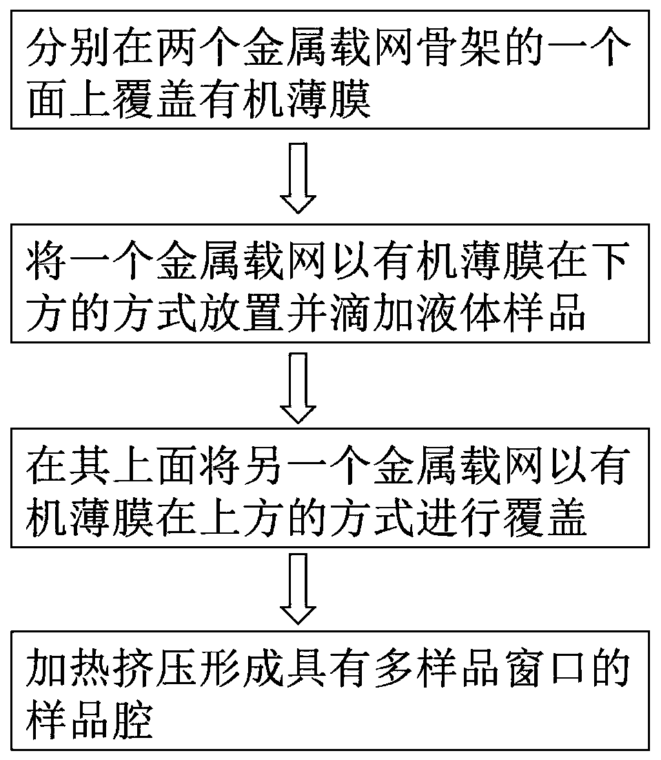
[0029] A preparation method for a liquid sample chamber characterized by transmission electron microscopy, the method comprising the following steps:
[0030] 1) Take two transmission electron microscopes with a diameter of 3mm to characterize the lead-tin-indium alloy grid skeleton with a melting point of 50°C. One surface of a lead-tin-indium alloy grid skeleton is covered with a 10nm thick square film to obtain a metal grid;
[0031] 2) Place one of the lead-tin-indium alloy grids on a flat heating platform with an organic film underneath, drop the liquid sample to be characterized from above the lead-tin-indium alloy grid, and then place an organic film on its surface cover another lead-tin-indium alloy carrier grid in a way;
[0032] 3) Heat the two lead-tin-indium alloy grids covered together until the lead-tin-indium alloy framework of the metal grid begins to soften, and then apply pressure perpendicular to the direction of the metal grid until the lead-tin-indium all...
Embodiment 2
[0036] A preparation method for a liquid sample chamber characterized by transmission electron microscopy, the method comprising the following steps:
[0037] 1) Take two lead-tin alloy grid skeletons with a melting point of 70°C for TEM characterization with a diameter of 3 mm. One surface of the lead-tin alloy grid skeleton is covered with a 30nm thick Fanghua film to obtain a metal grid;
[0038] 2) Place one of the lead-tin alloy grids on a flat heating table with the organic film on the bottom, drop the liquid sample to be characterized from above the lead-tin alloy grid, and then place the organic film on its surface. Overlay another pewter grid;
[0039] 3) Heat the two lead-tin alloy grids covered together until the lead-tin alloy skeleton of the metal grid begins to soften, and then apply pressure perpendicular to the direction of the metal grid until the lead-tin skeletons are fused with each other. A sealed liquid sample window is formed in the cross grid of the l...
Embodiment 3
[0043] A preparation method for a liquid sample chamber characterized by transmission electron microscopy, the method comprising the following steps:
[0044]1) Take two bismuth-tin alloy grid skeletons with a diameter of 3 mm for characterization with a melting point of 80 ° C, the mesh number of which is 800 mesh, the internal mesh is square holes, and the thickness of the skeleton is 18 μm. One surface of the bismuth-tin alloy grid skeleton is covered with a 10nm thick collodion film to obtain a metal grid;
[0045] 2) Place one of the bismuth-tin alloy grids on a flat heating table with the organic film on the bottom, drop the liquid sample to be characterized from above the bismuth-tin alloy grid, and then place the organic film on its surface Cover another bismuth-tin alloy grid;
[0046] 3) Heat the two bismuth-tin alloy grids covered together until the bismuth-tin alloy skeleton of the metal grid begins to soften, and then apply pressure perpendicular to the direction...
PUM
| Property | Measurement | Unit |
|---|---|---|
| melting point | aaaaa | aaaaa |
| thickness | aaaaa | aaaaa |
| thickness | aaaaa | aaaaa |
Abstract
Description
Claims
Application Information
 - R&D
- Intellectual Property
- Life Sciences
- Materials
- Tech Scout
- Unparalleled Data Quality
- Higher Quality Content
- 60% Fewer Hallucinations
Browse by: Latest US Patents, China's latest patents, Technical Efficacy Thesaurus, Application Domain, Technology Topic, Popular Technical Reports.
© 2025 PatSnap. All rights reserved.Legal|Privacy policy|Modern Slavery Act Transparency Statement|Sitemap|About US| Contact US: help@patsnap.com


