Novel cable insulation layer repairing machine

An insulating layer and cable technology, which is used in conductor/cable insulation, insulated/armored cable repair equipment, cable/conductor manufacturing, etc., and can solve problems such as difficult to control hot air temperature, unstable hot air process, and uneven hot air temperature. , to achieve low requirements for workers to repair skills and experience, reduce the time required for worker training, and improve the effect that is difficult to control

Pending Publication Date: 2019-12-31
GUANGZHOU NANYANG CABLE
View PDF0 Cites 1 Cited by
  • Summary
  • Abstract
  • Description
  • Claims
  • Application Information

AI Technical Summary

Problems solved by technology

[0003] The existing method of repairing the cable insulation layer is to heat the heat-shrinkable sleeve with a hot-air plastic welding torch, so that the heat-shrinkable tube shrinks and tightly covers the interface of the bare copper conductor for repair. Using this method for repairing, there are currently the following problems: hot air The temperature is difficult to control, the hot air process is unstable, and it is easy to form local scorching. The uneven temperature of the hot air makes the bonding of the heat shrinkable sleeve on the surface of the copper conductor not tightly sealed, and it is difficult to pass the water immersion resistance test. At present The heat-shrinkable tubing on the market does not meet the standard value of insulation thickness, resulting in the thickness of the repaired insulation layer being too thin, and the wall thickness of the heat-shrinkable tubing after heating and shrinking and cooling is difficult to control to meet the requirements of the standard value of insulation thickness. As a result, the thickness of the repaired insulation layer is too thin. The insulation material of the heat shrinkable sleeve and the insulation material to be repaired belong to different materials, which are consistent with the insulation material required by the corresponding product standards. When the boss is formed, the outer diameter becomes larger, and the outer diameter cannot be kept consistent. The boss has a great influence on the subsequent production overmolding (such as the cable forming process, etc.)

Method used


Image

  • Novel cable insulation layer repairing machine
  • Novel cable insulation layer repairing machine

Examples


Embodiment Construction

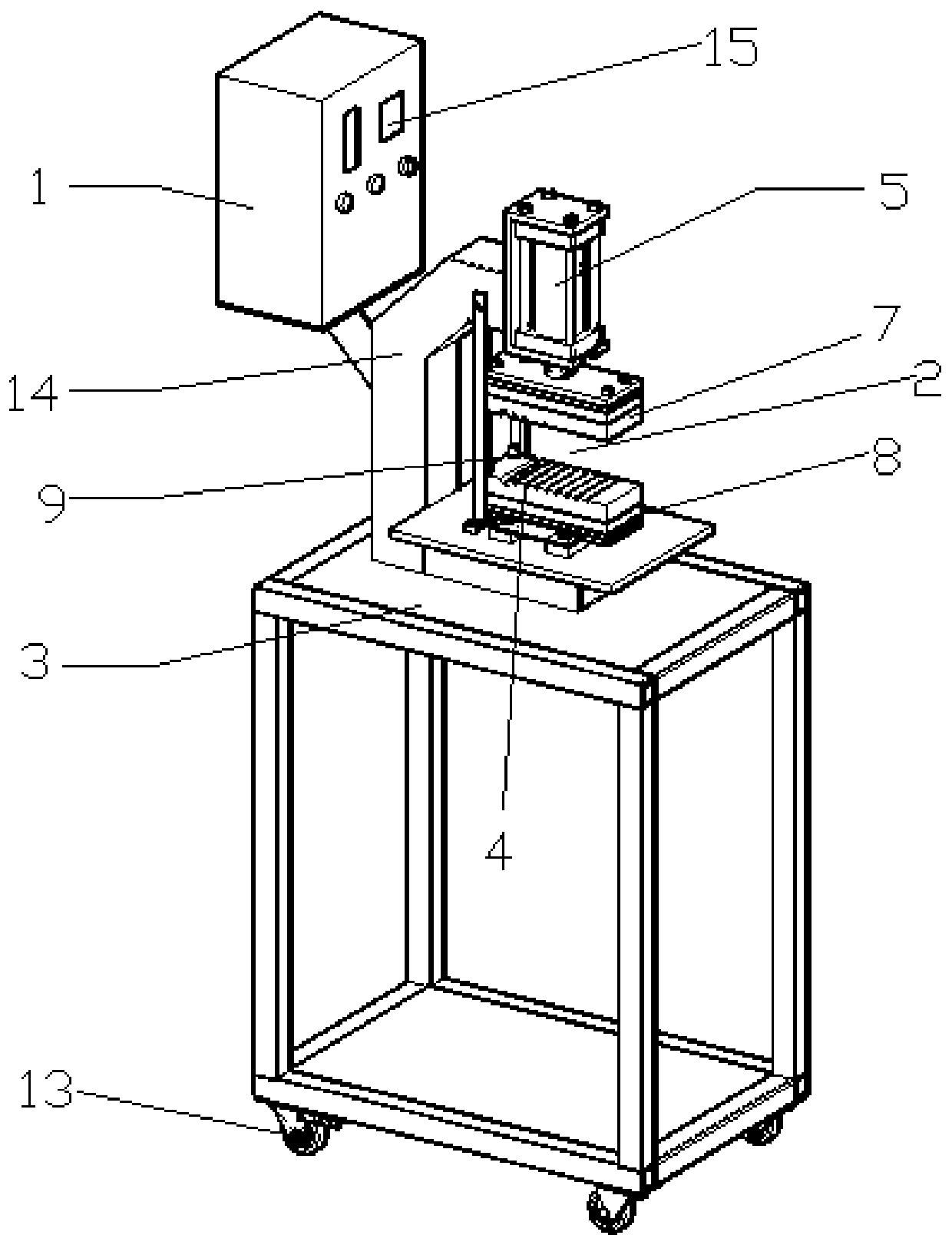
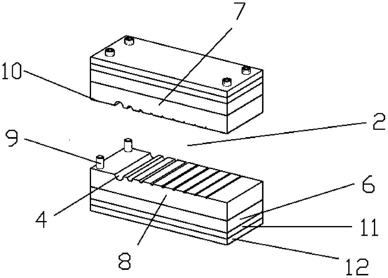
[0020] Attached below figure 1 To attach figure 2 To further illustrate the present invention, a new type of cable insulation repairing machine includes a power supply device 1 for supplying and controlling power, a cable mold 2 for repairing cable insulation, and a working platform 3. The wire The cable mold 2 is provided with a cable supplementary hole 4, and the cable mold 2 is provided with a driving device 5 for driving the opening and closing of the cable mold 2 and exerting pressure on the cable. The heating structure 6 of the cable mold 2 is heated, and the driving device 5 and the heating structure 6 are both electrically connected to the power supply device 1 .

[0021] The cable mold 2 includes an upper mold 7 and a lower mold 8, the upper mold 7 is connected with the driving device 2, the lower mold 8 is fixed on the working platform 3, a supporting plate is set on the working platform 3, and the lower mold 8 By arranging the base to be fixed on the supporting p...


PUM


Abstract

The invention discloses a novel cable insulation layer repairing machine, which includes a power supply device for supplying and controlling power, a cable mold for repairing a cable insulation layer,and a working platform. The cable mold is provided with a cable repairing hole, a driving device for opening and closing the cable mold, a heating structure for heating the mold. The driving device and the heating structure are both electrically connected to the power supply device. After the cable mold is heated to a certain temperature by the heating structure, a temperature value can be set inadvance, and then a cable to be repaired is placed on the cable repairing hole of the cable mold for fusion and crimping repair. The novel cable insulation layer repairing machine is easy to operate.The repaired cable is stable and reliable in performance.

Description

technical field [0001] The invention relates to the technical field of cable repair, and more specifically, to a novel cable insulation layer repairing machine. Background technique [0002] In the production process of wires and cables, there are two wire cores of the same specification connected, and there are local defects in the cable insulation layer. When two bare copper conductors are connected, the insulation layer needs to be repaired at the interface. When the insulation When a local defect occurs in the layer, the defective part can be trimmed with a knife to form a section of bare conductor, and then repaired. [0003] The existing method of repairing the cable insulation layer is to heat the heat-shrinkable sleeve with a hot-air plastic welding torch, so that the heat-shrinkable tube shrinks and tightly covers the interface of the bare copper conductor for repair. Using this method for repairing, there are currently the following problems: hot air The temperatu...

Claims


Application Information

Patent Timeline
Patent Type & Authority Applications(China)
IPC IPC(8): H01B13/14H01R43/02H01R43/00H02G1/16
CPCH01B13/143H01B13/144H01B13/145H01R43/005H01R43/0207H02G1/16
Inventor 周建邱湘伟李楷纯曹新甫刘明全林晓峰欧阳湘璋杨洪文邓伟杰
Owner GUANGZHOU NANYANG CABLE
Why Eureka
Try Eureka