Resonant equalization circuit with controllable equalization voltage difference and control method

A technology of equalizing voltage and equalizing circuit, applied in the direction of charge equalizing circuit, battery circuit device, circuit device, etc., to ensure the effect of equalizing speed

Pending Publication Date: 2019-12-31
SOUTHWEST JIAOTONG UNIV
View PDF0 Cites 2 Cited by
  • Summary
  • Abstract
  • Description
  • Claims
  • Application Information

AI Technical Summary

Problems solved by technology

However, when the voltage difference between the batteries is reduced, similar problems to the switched capacitor balance circuit still exist in the resonant switched capacitor balance circuit

Method used


Image

  • Resonant equalization circuit with controllable equalization voltage difference and control method
  • Resonant equalization circuit with controllable equalization voltage difference and control method
  • Resonant equalization circuit with controllable equalization voltage difference and control method

Examples


Embodiment 1

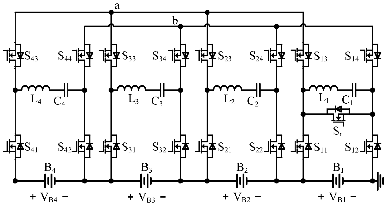
[0058]Taking the equalization circuit with 4 batteries and all resonant switches as a single MOS transistor as embodiment 1, the circuit structure diagram is as follows figure 2 shown. Assuming initial battery voltage V B4 >V B3 >V B2 >V B1 , and ΔV Bmax >ΔV 1 . At this time, the equalization circuit works in equalization mode 1. The two working states of the equalization circuit in this equalization mode are as follows:

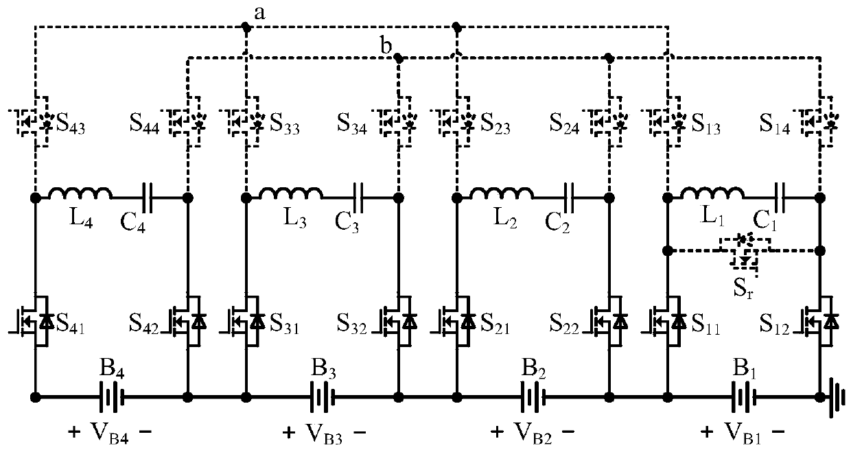
[0059] (1) Working state I: the control signal controls the resonant switch S 11 , S 12 , S 21 , S 22 , S 31 , S 32 , S 41 , S 42 turn on; at the same time control the rest of the resonant switch and the self-resonant switch to turn off; if Figure 3a shown. Energy passes through the inductor L m in battery B m and capacitance C m Transmission between; among them, m=1,2,3,4.

[0060] (2) Working state Ⅱ: the control signal controls the resonant switch S 13 , S 14 , S 23 , S 24 , S 33 , S 34 , S 43 , S 44 turn on; at the same tim...

Embodiment 2

[0070] The equalization circuit of two MOS tubes connected with 4 batteries and a part of the resonant switch as the source is the embodiment 2, and its circuit structure is as follows Figure 7 shown. Assuming initial battery voltage V B4 >V B3 >V B2 >V B1 , and ΔV Bmax >ΔV 1 . At this time, the equalization circuit works in equalization mode 1. The two working states of the equalization circuit in this equalization mode are as follows:

[0071] (1) Working state I: According to the detected battery voltage, the battery with the highest voltage is B k (k=1,2,3,4); the control signal controls the resonant switch S k1 , S k2 , S 13 , S 14 , S 23 , S 24 , S 33 , S 34 , S 43 , S 44 and self-resonant switch S r turn off; at the same time control the rest of the resonant switch conduction. Figure 8a Shown, is the battery B 4 The working state of the equalization circuit at the highest voltage, in which the resonant switch S 11 , S 12 , S 21 , S 22 , S 31 ...


PUM


Abstract

A resonant equalization circuit with a controllable equalization voltage difference and a control method are disclosed. The resonant equalization circuit includes more than three resonant switched capacitor units having the same structure. Each resonant switched capacitor unit is equipped with a battery. The resonant equalization circuit further includes a self-resonant switch having a first terminal and a second terminal connected to the second terminal of the second resonant switch and the second terminal of the first resonant switch of any one of the resonant switched capacitor units, respectively. The resonant equalization circuit has two working phases. In the first phase, the resonant equalization circuit can realize energy transmission between all the batteries, and quickly reducesthe voltage difference between the batteries to a mode switching threshold. In the second phase, the resonant equalization circuit can realize the energy transmission between the battery with the highest voltage and the battery with the lowest voltage. Further, due to the effect of the self-resonant switch, the equalization circuit still has a large equalization current when the voltage differencebetween the batteries is small, thereby ensuring the equalization speed. By controlling a switching threshold of the two modes, different equalization speeds can be obtained to meet the needs of different equalization occasions.

Description

technical field [0001] The invention relates to the technical field of lithium battery / supercapacitor voltage equalization, in particular to a resonant equalization circuit with controllable equalized voltage difference and a control method. Background technique [0002] As energy storage components, lithium batteries and supercapacitors are widely used in electric vehicles, distributed power generation systems and other fields. The rated voltage of a single lithium battery / supercapacitor (for convenience of description, hereinafter collectively referred to as a battery) is low, so a large number of batteries are usually used in series to provide a sufficient voltage for the load. However, due to manufacturing reasons, battery cells have inconsistencies in performance such as internal resistance, voltage, and capacity. When the battery pack is charging and discharging, this inconsistency will cause the inconsistency of the battery cell voltage, which will lead to the waste ...

Claims


Application Information

Patent Timeline
Patent Type & Authority Applications(China)
IPC IPC(8): H02J7/00
CPCH02J7/0019
Inventor 张小兵周国华高凯田庆新徐顺刚
Owner SOUTHWEST JIAOTONG UNIV
Why Eureka
Try Eureka