Slurry transfer method, polyolefin production method and utilization thereof

A slurry and aliphatic hydrocarbon technology, applied in the field of slurry transfer, polyolefin production and utilization, can solve the problems of inability to completely eliminate clogging, transfer, and inability to slurry, achieve long-term and stable operation, reduce Raw material loss, blocking effect

Active Publication Date: 2022-05-17
SUMITOMO CHEM CO LTD
View PDF23 Cites 0 Cited by
  • Summary
  • Abstract
  • Description
  • Claims
  • Application Information

AI Technical Summary

Problems solved by technology

[0009] However, in the slurry transfer pumps having the structures described in Patent Documents 1 and 2 as described above, there is still the following problem: the clogging caused by the slurry in the check valve cannot be completely eliminated, and the slurry cannot be transferred. transfer, it is necessary to stop the operation of the mechanical equipment frequently to clean the inside of the pump

Method used


Image

  • Slurry transfer method, polyolefin production method and utilization thereof
  • Slurry transfer method, polyolefin production method and utilization thereof
  • Slurry transfer method, polyolefin production method and utilization thereof

Examples


preparation example Construction

[0121] Examples of the metallocene compound used in the preparation of the metallocene-based solid catalyst include transition metal compounds represented by the following general formula.

[0122] L x m

[0123] (In the formula, M represents a transition metal compound. x represents a numerical value that satisfies the atomic valence of the transition metal M. L is a ligand coordinated with the transition metal, and at least one of L is a ligand having a cyclopentadiene skeleton .)

[0124] As said M, atoms of Groups 3 to 6 of the Periodic Table of Elements (IUPAC 1989) are preferable, and titanium, zirconium, and hafnium are more preferable.

[0125] Ligands having a cyclopentadienyl skeleton as L include (substituted) cyclopentadienyl, (substituted) indenyl, (substituted) fluorenyl, etc. Specifically, cyclopentadienyl, methyl Cyclopentadienyl, tert-butylcyclopentadienyl, dimethylcyclopentadienyl, tert-butylmethylcyclopentadienyl, methylisopropylcyclopentadienyl, trimethy...

Embodiment 1

[0186] (1) Preparation of solid catalyst components

[0187] After replacing the 100 mL flask equipped with the stirrer, dropping funnel, and thermometer with nitrogen, 36.0 mL of toluene and 22.5 mL of titanium tetrachloride were put into this flask, and it stirred. After setting the temperature in the flask to 0° C., 1.88 g of magnesium ethoxide was added at intervals of 30 minutes at this temperature, four times in total, and then stirred at 0° C. for 1.5 hours. Next, 0.60 mL of ethyl 2-ethoxymethyl-3,3-dimethylbutyrate was put into the flask, and thereafter, the temperature in the flask was raised to 10°C. Thereafter, the mixture was stirred at this temperature for 2 hours, and 9.8 mL of toluene was added. Next, the temperature in the flask was raised at a rate of 1.2 K / min, and 3.15 mL of ethyl 2-ethoxymethyl-3,3-dimethylbutyrate was put into the flask at a time of 60° C., and the temperature was raised to 110°C. The components put into the flask were stirred at this t...

Embodiment 2

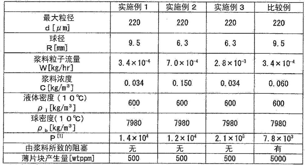
[0200] In the preparation of the above (2) prepolymerization catalyst, the slurry concentration C of the prepolymerization catalyst is adjusted to 0.150kg / m 3 , in the transfer of the above (3-1) slurry, the diameter R of the ball in the plunger pump is set to 6.3 mm, and in the above (3-2) polymerization of polypropylene, the slurry transferred to the first tank The particle flow W of the material is set to 7.0×10 -4 kg / hr, except that, the same operation as in Example 1 was carried out to produce a polypropylene powder. To illustrate, using P=W(ρ l / (ρ b -ρ l )) 0.5 / (C d(d+R)R 0.5 ) calculated value is 1.2×10 4 , satisfying the conditions of formulas (1)-(3).


PUM

PropertyMeasurementUnit
diameteraaaaaaaaaa
particle diameteraaaaaaaaaa
particle sizeaaaaaaaaaa

Abstract

The present invention realizes a slurry transfer method capable of stably operating a plunger pump that supplies slurry at high pressure for a long period of time. A method for transferring slurry, wherein a transfer pump equipped with a ball check valve is operated under the conditions satisfying the following formula (1) to transfer the slurry containing particles and liquid, 7.8×10 3 <P≤5.0×10 5 (1). Here, P=W(ρ 1 / (ρ b -ρ 1 )) 0.5 / (C d(d+R)R 0.5 ), in formula (1), W represents the particle flow rate (kg / hr) in the slurry passing through the ball check valve, and C represents the particle concentration (kg / m 3 ), d represents the maximum particle diameter (m) of the particles in the slurry, R represents the ball diameter (m) of the one-way valve, ρ 1 Indicates the density of the liquid (kg / m 3 ), ρ b Indicates the density of the ball of the check valve (kg / m 3 ).

Description

technical field [0001] The present invention relates to a method for transferring slurry, a method for producing polyolefin, and its utilization. Background technique [0002] The transfer of the slurry can be widely used in industrial fields such as the chemical industry for a process that requires supply of a slurry containing solid particles. [0003] For example, Patent Documents 1 and 2 describe a method of preventing stagnation and accumulation of coarse particles in a check valve by setting the gap between the ball of the check valve and the guide rail to be greater than or equal to a certain size. [0004] prior art literature [0005] patent documents [0006] Patent Document 1: Japanese Patent Application Laid-Open No. 6-017942 (published on January 25, 1994) [0007] Patent Document 2: International Publication No. 2012 / 013800 (published on February 2, 2012) Contents of the invention [0008] The problem to be solved by the invention [0009] However, in th...

Claims


Application Information

Patent Timeline
Patent Type & Authority Patents(China)
IPC IPC(8): B01J8/00C08F110/06
CPCB01J8/0015C08F110/06B01J2208/00743C08F2/01B01J8/002B01J2204/002B01J2219/00247C08F2/001C08F2/14C08F4/651C08F4/6546B01J8/0045B01J2208/00938C08F10/06C08F10/08C08F10/14
Inventor 田中直广糸口聪
Owner SUMITOMO CHEM CO LTD
Why Eureka
Try Eureka