A high-speed synchronous belt sewing machine

A high-speed synchronization, sewing machine technology, applied in sewing machine components, sewing machine needle holders, sewing machine thread take-up devices, etc. Quality, improved service life, long service life effect

Active Publication Date: 2021-06-25
东莞市缝神机械设备有限公司
View PDF0 Cites 0 Cited by
  • Summary
  • Abstract
  • Description
  • Claims
  • Application Information

AI Technical Summary

Problems solved by technology

However, with the continuous emergence of new types of chemical fiber fabrics and the continuous changes in people's needs, higher and higher requirements have been put forward for the performance of the sewing machine, and the original structures of various sewing machines have gradually shown their disadvantages.
[0003] The transmission structure of ordinary disc sewing machine generally includes a main shaft installed on the platform and an auxiliary shaft installed on the bracket. The end of the main shaft is equipped with a first bevel gear, and the end of the auxiliary shaft is installed with a second bevel gear. The second bevel gear and the first bevel gear are meshed and interlocked to achieve the driving purpose between the auxiliary shaft and the main shaft, but the second bevel gear and the first bevel gear need to be lubricated, and the wear is relatively large , the noise is also large, which affects the high-speed operation of the sewing machine; moreover, the auxiliary shaft and the main shaft are linked through the bevel gear structure, and the longitudinal interval between them is extremely small, resulting in excessive gap between the lower end of the bracket and the dial. The space of the sheet is small, which makes it inconvenient to operate when sewing thick sweaters or thick materials, which affects work efficiency

Method used


Image

  • A high-speed synchronous belt sewing machine
  • A high-speed synchronous belt sewing machine
  • A high-speed synchronous belt sewing machine

Examples


Embodiment Construction

[0036] The present invention will be further described below in conjunction with specific embodiments and accompanying drawings.

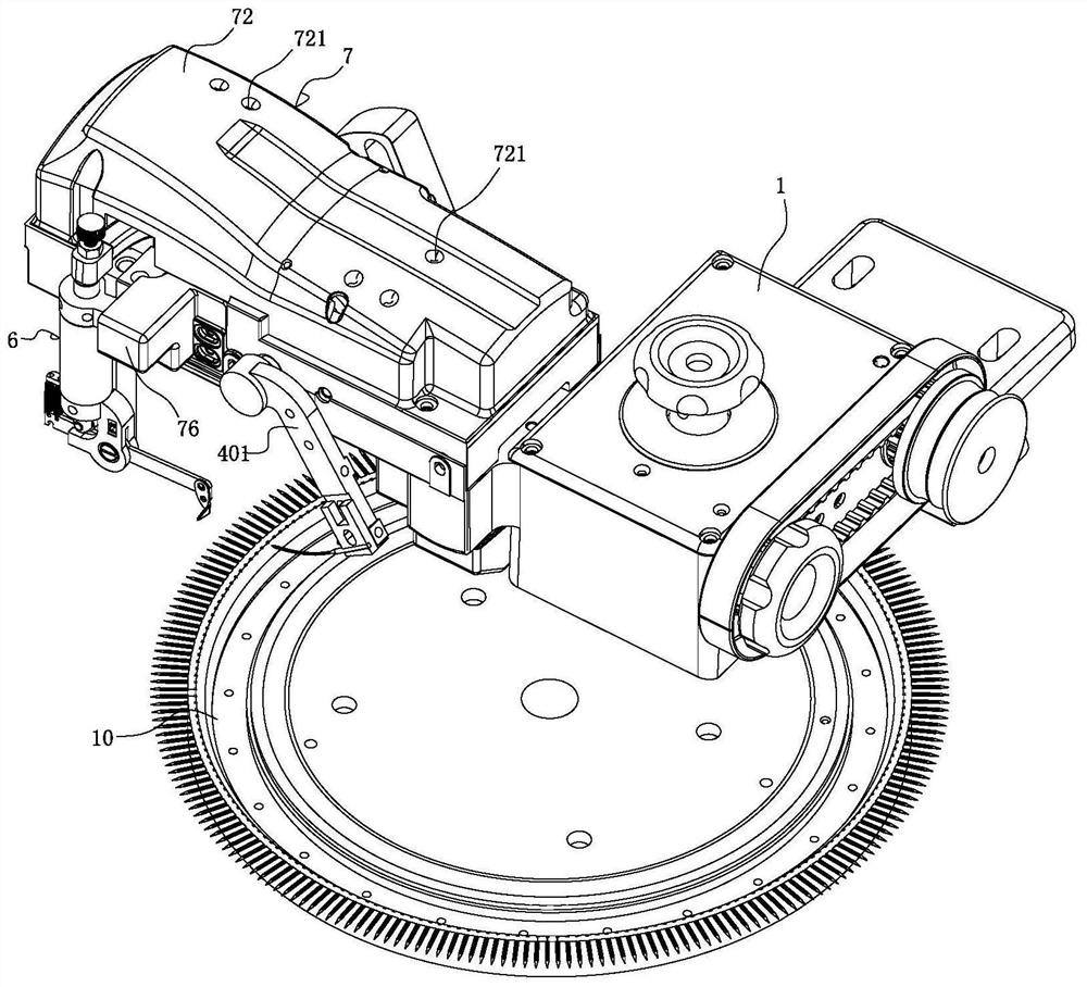
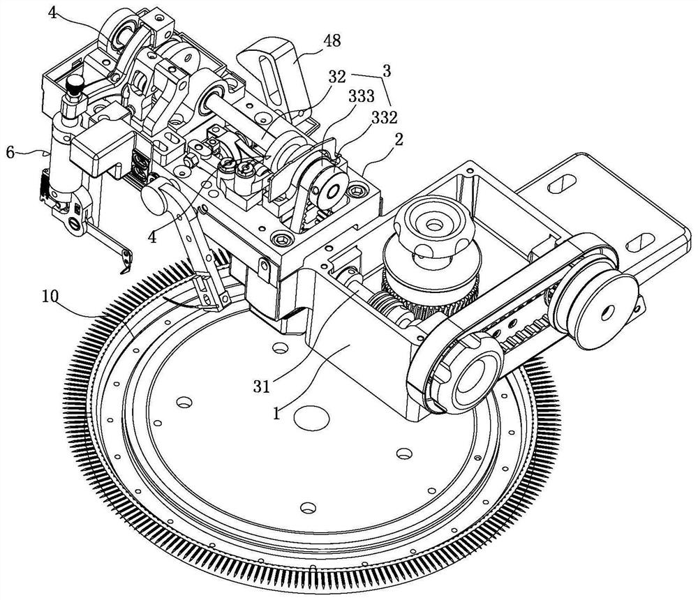
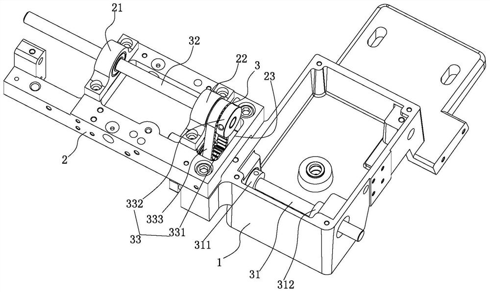
[0037] See Figure 1-12 As shown, it is a high-speed synchronous belt sewing machine, which includes: a vehicle platform 1, a bracket 2 installed on the vehicle platform 1, a dial 10 installed on the lower end of the bracket 2, a vehicle platform 1 and a bracket The synchronous belt transmission structure 3 on the 2, the needle pendulum transmission structure 4 installed on the bracket 2 and driven by the synchronous belt transmission structure 3, the needle arm 401 installed on the needle pendulum transmission structure 4, the needle arm 401 installed on the And the large needle 402 adapted to the dial 10, the thread take-up transmission mechanism 5 driven by the synchronous belt transmission structure 3 installed on the support 2, the thread take-up device 6 connected with the thread take-up transmission mechanism 5, installed on the The oil sto...


PUM


Abstract

The invention discloses a high-speed synchronous belt sewing machine, which comprises: a vehicle platform, a bracket installed on the vehicle platform, a dial mounted on the lower end of the bracket, a synchronous belt transmission structure installed on the vehicle platform and the bracket, The needle swing transmission structure installed on the bracket, the needle arm and the large needle installed on the needle swing transmission structure, the thread take-up transmission mechanism installed on the bracket, the thread take-up device connected with the thread take-up transmission mechanism, and the thread take-up device installed on the bracket Peripheral oil storage lubrication structure, the synchronous belt transmission structure includes the main shaft installed on the platform, the auxiliary shaft installed on the bracket and the synchronous belt assembly installed between the main shaft and the auxiliary shaft, the synchronous belt assembly includes The first synchronous wheel at the end, the second synchronous wheel installed at the end of the countershaft, and the synchronous belt installed between the first synchronous wheel and the second synchronous wheel, the bracket is installed on the side of the upper end of the platform, so that the bracket and the car A longitudinal interval is formed between the platforms; the side of the platform is provided with a reinforced bearing seat for supporting the end of the main shaft.

Description

Technical field: [0001] The invention relates to the technical field of sewing machines, in particular to a high-speed synchronous belt sewing machine. Background technique: [0002] The sewing machine is one of the important equipment in the wool weaving industry, which is used to sew knitted garment pieces, collars, cuffs, etc. In order to simplify the structure of the seaming machine and improve the working efficiency of the seaming machine, people have made a lot of efforts and achieved great results. But along with the continuous appearance of new chemical fiber fabrics and the constant change of people's needs, higher and higher requirements have been put forward for the performance of the seaming machine, and the original various seaming machine structures have gradually shown their disadvantages. [0003] The transmission structure of ordinary disc sewing machine generally includes a main shaft installed on the vehicle platform and a sub-shaft installed on the brack...

Claims


Application Information

Patent Timeline
Patent Type & Authority Patents(China)
IPC IPC(8): D05B7/00D05B69/00D05B55/14D05B49/00D05B71/00
CPCD05B7/00D05B49/00D05B55/14D05B69/00D05B71/00
Inventor 邓镰桂
Owner 东莞市缝神机械设备有限公司
Why Eureka
Try Eureka