
Eddy current-based rotation angle measuring device

A technology of rotation angle measurement and eddy current, which is applied in the direction of measuring devices, electric devices, and electromagnetic means, etc., can solve the problems of circular grating angle measurement accuracy improvement, high price, high machining accuracy and installation accuracy of mechanical axis, and achieve measurement Expanded range, improved measurement accuracy, and convenient implementation

Active Publication Date: 2020-01-03
北京瑞控信科技股份有限公司
View PDF5 Cites 2 Cited by
  • Summary
  • Abstract
  • Description
  • Claims
  • Application Information

AI Technical Summary

Problems solved by technology

[0006] Among the three types of angle sensors, the circular grating has the advantages of good dynamic performance of measurement, strong anti-interference ability, and high measurement accuracy. The disadvantage is that it requires high machining accuracy and installation accuracy of the mechanical axis, and its price is relatively high.
[0007] The current circular grating with the highest angle measurement accuracy, due to the limitation of the photolithography process, makes it difficult to improve the angle measurement accuracy of the circular grating, especially for the small radius circular grating, its angle measurement accuracy has become a limiting instrument in many precision measuring instruments Key Factors for Accuracy

Method used


Image

  • Eddy current-based rotation angle measuring device
  • Eddy current-based rotation angle measuring device
  • Eddy current-based rotation angle measuring device

Examples


Embodiment Construction

[0030] In order to make the objectives, technical solutions and advantages of the present invention clearer, the present invention will be further described in detail below with reference to the specific embodiments and the accompanying drawings. It should be understood that these descriptions are exemplary only and are not intended to limit the scope of the invention. Also, in the following description, descriptions of well-known structures and techniques are omitted to avoid unnecessarily obscuring the concepts of the present invention.

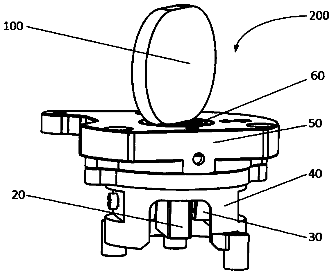
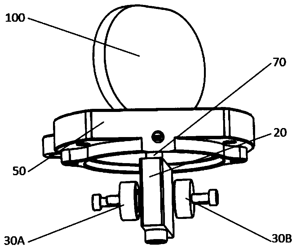
[0031] figure 1 is the three-dimensional view of the one-dimensional rotation angle measuring device based on the eddy current of the present invention, figure 2 Yes figure 1 A perspective view of the rotation angle measuring device shown with the sensor holder removed. from figure 1 and figure 2It can be seen that the rotation angle measuring device 200 mainly includes a fixed part and a rotating part, wherein the fixed part mainly ...


PUM


Abstract

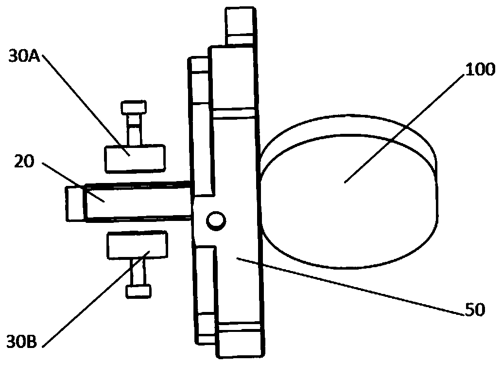
An eddy current-based rotation angle measuring device is provided. The eddy current-based rotation angle measuring device comprises a fixed portion and a rotating portion; the fixed portion comprisesan eddy current sensor, a sensor fixing frame, and a base; the rotating portion comprises a steering mirror and a swinging piece; the swinging piece is fixedly connected with the steering mirror through a deep groove ball bearing and a pin; the swinging piece swings with the rotation of the steering mirror; and the steering mirror is driven by a voice coil motor or a piezoelectric ceramic motor toform different rotation angles. During the rotation of the steering mirror, the change in the distance between the eddy current sensor and the swinging piece will form a pair of differential signalsto change the inductance of the eddy current, so that the change in the distance and the change in the angle of the steering mirror are obtained through the change in the inductance, and the purpose of rotation angle measuring is achieved. The rotation angle measuring device provided by the present invention has a simple structure, a measurement range is large and adjustable, angle measuring accuracy is high, and batch manufacturing can be realized in a facilitated manner.

Description

technical field [0001] The invention relates to the technical field of photoelectric scanning and tracking, in particular to a rotational angle measuring device. Background technique [0002] The goniometer sensor is a commonly used geometric quantity sensor, which is widely used in many fields such as aerospace, industrial production, machinery manufacturing and military science. At present, the mainstream angle measuring sensors on the market include photoelectric encoders, resolvers and disc-type inductive synchronizers. [0003] The photoelectric encoder is commonly known as the circular grating, which uses the moire fringes generated by the circular grating and the photoelectric conversion technology to output the angle information in the form of pulses. Compared with other goniometer sensors, the circular grating has the advantages of small size, light weight, high measurement accuracy, fast response speed, strong anti-interference ability, and convenient use, and has...

Claims


Application Information

Patent Timeline
IPC IPC(8): G01B7/30
CPCG01B7/30
Inventor 肖立亮孔凡辉
Owner 北京瑞控信科技股份有限公司
Learn More