Shuttered adaptor for optical connector

A technology of optical connectors and adapters, which is applied in the coupling of optics, optical components, and optical waveguides, can solve the problems of small component size, burden of assembly process, and influence of molding process, so as to avoid mutual contact, facilitate manufacturing process, The effect of reducing complexity

Pending Publication Date: 2020-01-03
连讯通信(天津)有限公司
View PDF1 Cites 2 Cited by
  • Summary
  • Abstract
  • Description
  • Claims
  • Application Information

AI Technical Summary

Problems solved by technology

[0005] However, although this can achieve the desired purpose, it increases the complexity of the manufacturing process because of ignoring the manufacturing conditions of the components.
For example, due to the small size of the shielding plate with grooves, it is necessary to precisely control its surface topography, that is, the corresponding relationship between the plane of the plate and the grooves, which will undoubtedly cause difficulties in the design and manufacture of the forming mold degree, it is also easy to affect the molding process, and cannot effectively control and maintain the yield of injection molding
[0006] Furthermore, the shielding plate 11 of this case is assembled at the opening portion 11d of the bottom plate 1c by a leaf spring 18. However, as mentioned above, the size of the components is relatively small, so it will also impose a burden on the assembly process.

Method used


Image

  • Shuttered adaptor for optical connector
  • Shuttered adaptor for optical connector
  • Shuttered adaptor for optical connector

Examples


Embodiment Construction

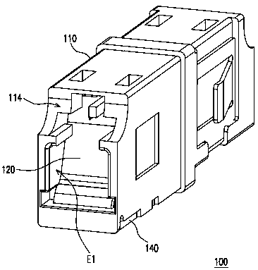
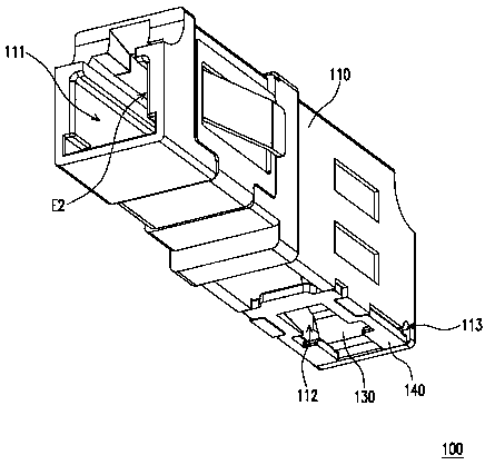
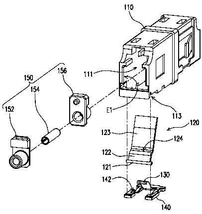
[0056] figure 1 is a schematic diagram of a light-shielding adapter according to an embodiment of the present invention. figure 2 Yes figure 1 Schematic diagram of the shading adapter in another view. image 3 and Figure 4 The exploded views of the light-shielding adapter are drawn from different viewing angles. Please also refer to Figure 1 to Figure 4 , in this embodiment, a light-shielding adapter 100 for an optical connector, which includes a body 110 , a shielding member 120 and an elastic member 130 . The body 110 has an accommodating space 111 . The shielding member 120 is movably assembled on the body 110 to shield or expose the accommodating space 111 . The elastic member 130 is disposed in the body 110 and located on a moving path of the shielding member 120 .

[0057] image 3 and Figure 4 The exploded views of the light-shielding adapter are drawn from different viewing angles. Please also refer to image 3 and Figure 4 , the optical connector 300 ...


PUM


Abstract

The invention relates to a shuttered adaptor for an optical connector, including a body having a receiving space, a shutter movably assembled to the body to shield or expose the receiving space, and an elastic member. An optical connector is suited for entering the receiving space and being connected in the body by pushing away the shutter. The shutter has a step structure to keep away from the optical connector via a gap. The elastic member is disposed in the body and located on a moving path of the shutter. The shutter deforms the elastic member while the optical connector pushes away the receiving space, and the elastic member drives the shutter to be restored while the optical connector leaves the receiving space.

Description

technical field [0001] The present invention relates to an adapter for a connector, and in particular to a light-shielding adapter for an optical connector. Background technique [0002] Due to the advantages of high bandwidth and low loss, optical fiber has been widely used as a signal transmission medium in recent years. Therefore, with the technical expansion of optical communication networks, wide area networks such as the Internet and intranets have become popular. To improve communication flow. [0003] The optical adapter is used to provide a connection medium for coupling optical connectors, and its purpose is to provide a closed environment when the optical connectors are mated with each other to avoid external interference. At the same time, it can also prevent the operator from directly seeing the light emitted by the optical connector, which would cause damage to the eyes. [0004] For example, US Pat. No. 9,453,963 B2 shows an optical adapter with a shielding ...

Claims


Application Information

Patent Timeline
Patent Type & Authority Applications(China)
IPC IPC(8): G02B6/38
CPCG02B6/3847G02B6/3849G02B6/3825G02B2006/4297G02B6/3813G02B6/3865G02B6/387G02B6/3893
Inventor 许焕彬萧智仁
Owner 连讯通信(天津)有限公司
Why Eureka
Try Eureka