Electricity taking device utilizing leakage current of valve plate of lightning arrester and working method thereof

A technology of leakage current and arrester, applied in the field of power supply, can solve the problem of power supply of arrester

Active Publication Date: 2020-01-03
XI AN JIAOTONG UNIV
View PDF7 Cites 3 Cited by
  • Summary
  • Abstract
  • Description
  • Claims
  • Application Information

AI Technical Summary

Problems solved by technology

[0005] The technical problem to be solved by the present invention is to provide a self-feeding device and its working m...

Method used


Image

  • Electricity taking device utilizing leakage current of valve plate of lightning arrester and working method thereof
  • Electricity taking device utilizing leakage current of valve plate of lightning arrester and working method thereof

Examples


Embodiment 1

[0050] 10kV surge arrester power-taking device

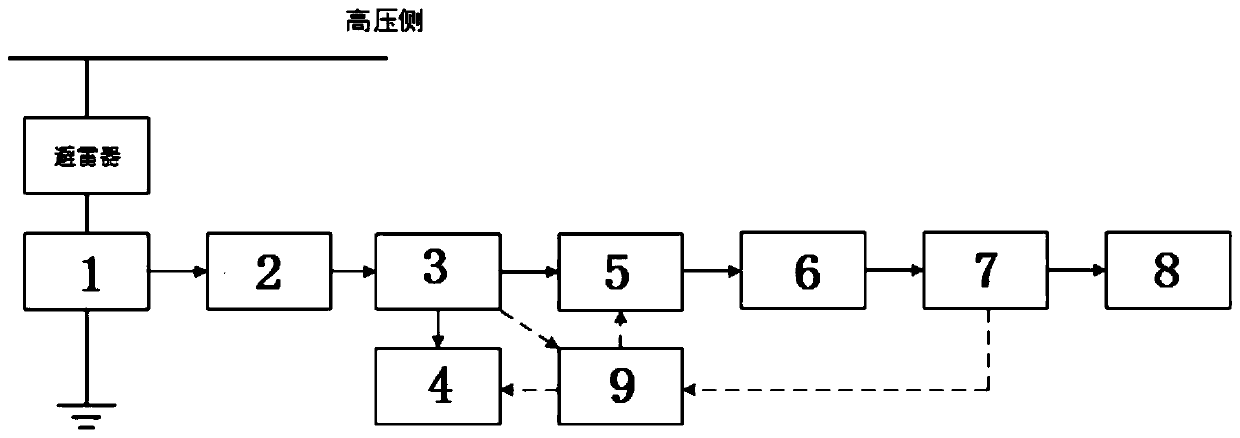
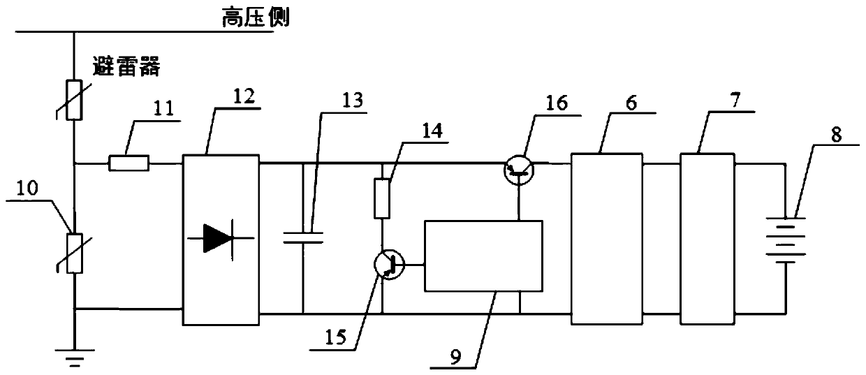
[0051] The power-taking device is installed between the 10kV arrester and the ground, which is used to supply power to loads such as arrester monitors after taking power from the leakage current in the arrester. Among them, the varistor 10 and the current limiting resistor 11 constitute the power-taking and protection module, the rectifier bridge 12 constitutes the rectification module, the energy storage capacitor 13 constitutes the energy storage module, the discharge resistor 14 and the first triode constitute the discharge module, and the second triode constitutes the discharge module. The triode 16 forms a switch module, and the single-chip microcomputer module 17, the DC-DC module 18, the battery management module 19 and the lithium battery pack 20 have the same functions as the corresponding modules in the present invention.

[0052] The varistor 10 has a varistor voltage of 90V and a flow of 10kA, which is used to absorb...

Embodiment 2

[0064] 35kV surge arrester power taking device

[0065] The power-taking device is installed between the 35kV arrester and the ground, which is used to supply power to loads such as arrester monitors after taking power from the leakage current in the arrester.

[0066] The varistor voltage of the varistor 10 is 90V, and the flow current is 20kA;

[0067] The current limiting resistor 11 is 100Ω;

[0068] Rectifier bridge 12 DC withstand voltage 150V;

[0069] The energy storage capacitor 13 is 1mF, and the DC withstand voltage is 150V;

[0070] The discharge resistor 14 is 50kΩ, and the withstand voltage of the first triode 15 is 150V.

[0071] The second triode 16 has a withstand voltage of 150V;

[0072] Single chip microcomputer 17 is MSP430F147;

[0073] The input voltage range of the DC-DC module 18 is 15-36V, and the output voltage is 24V;

[0074] The battery management module 19 has an input voltage range of 7.5-28V, and has the functions of temperature monitorin...

Embodiment 3

[0078] 110kV surge arrester power taking device

[0079] The power taking device is installed between the 110kV arrester and the ground, which is used to supply power to loads such as the arrester monitor after taking power from the leakage current in the arrester.

[0080] The varistor voltage of the varistor 10 is 90V, and the flow current is 50kA;

[0081] The current limiting resistor 11 is 100Ω;

[0082] Rectifier bridge 12 DC withstand voltage 150V;

[0083] The energy storage capacitor 13 is 1mF, and the DC withstand voltage is 150V;

[0084] The discharge resistor 14 is 50kΩ, and the withstand voltage of the first triode 15 is 150V.

[0085] The second triode 16 has a withstand voltage of 150V;

[0086] Single chip microcomputer 17 is MSP430F147;

[0087] The input voltage range of the DC-DC module 18 is 12-36V, and the output voltage is 24V;

[0088] The battery management module 19 has an input voltage range of 7.5-28V, and has the functions of temperature moni...


PUM

PropertyMeasurementUnit
Current limiting resistoraaaaaaaaaa

Abstract

The invention discloses an electricity taking device utilizing the leakage current of a valve plate of a lightning arrester and a working method thereof. The leakage current in the valve plate of thelightning arrester is collected through an electricity taking and protecting module, that an electricity taking circuit is not affected when the lightning arrester acts and high-amplitude impact current occurs is guaranteed, and an energy storage module is charged after the leakage current is rectified; when a voltage of the energy storage module reaches a first set value, a single-chip microcomputer module controls a switch module to be switched on, and a battery is charged through a DC-DC module and a battery management module; when the voltage of the energy storage module drops to a secondset value, the single-chip microcomputer module controls the switch module to be turned off, and the energy storage module enters a charging state again; when the lithium battery pack is fully charged, the single-chip microcomputer module conducts a discharge module according to the electric quantity information provided by the battery management module when the electric quantity of the lithium battery is saturated, so the energy storage module discharges energy, and the power output of the DC-DC module is locked; the battery management module ensures over-charge and over-discharge protection,input under-voltage protection, chip over-temperature protection and current-limiting protection of the battery.

Description

technical field [0001] The invention belongs to the technical field of power supplies, and in particular relates to a self-power-taking device and a working method thereof utilizing leakage current from a valve plate of a lightning arrester. Background technique [0002] With the construction of the ubiquitous power Internet of Things, the demand for various smart terminals continues to expand. At present, 540 million smart meters and other monitoring devices in the power Internet of Things have been connected, and billions of smart terminals will be equipped in the power grid in the future. In the ubiquitous power Internet of Things, the online monitoring of arresters is quite necessary. The arrester may increase the leakage current of the arrester due to poor sealing and valve aging, which will further cause the valve to overheat, which may cause accidents such as explosion of the arrester. Online monitoring is an important part of building ubiquitous power Internet of Thi...

Claims


Application Information

Patent Timeline
IPC IPC(8): H02H1/06H02H9/04H02J7/00G01R19/165
CPCG01R19/165H02H1/063H02H9/041H02J7/0029
Inventor 杨兰均史宇昊
Owner XI AN JIAOTONG UNIV
Why Eureka
Try Eureka