Capacitive elastic strain sensor, preparation method thereof and application

An elastic strain and capacitive technology, applied in the direction of sensors, chemical instruments and methods, applications, etc., can solve the problems of poor elastic strain, complex process, poor human body fit, etc., achieve low thickness, improve performance stability, and improve reliability. The effect of wearability and comfort

Pending Publication Date: 2020-01-07
NINGBO ELASTECH CO LTD
View PDF0 Cites 14 Cited by
  • Summary
  • Abstract
  • Description
  • Claims
  • Application Information

AI Technical Summary

Problems solved by technology

[0004] The currently reported capacitive elastic strain sensors mainly have two structures. One is to use a polymer elastomer and a certain shape of metal or conductive fiber to form a capacitive structure. This structure has poor elastic strain and the range of measuring tensile strain is limited. The other is to form a capacitive structure by combining polymer elastomers with ductile conductors such as liquid metals. This structure generally ad...

Method used


Image

  • Capacitive elastic strain sensor, preparation method thereof and application
  • Capacitive elastic strain sensor, preparation method thereof and application

Examples


Embodiment 1

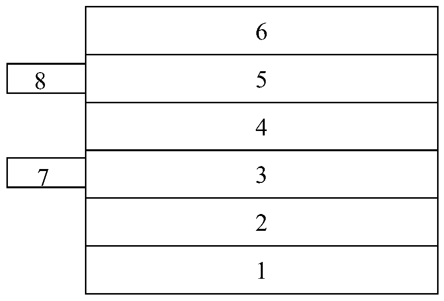
[0047] In this embodiment, the structure of the capacitive elastic strain sensor is as follows figure 1 As shown, the elastic textile material is used as the matrix, and is composed of an elastic bonding layer, a first conductive layer, a second conductive layer, an elastic dielectric layer and an elastic encapsulation layer. The elastic bonding layer is conductive and insulating, and is located on the surface of the substrate; the first conductive layer is located on the surface of the elastic body bonding layer, is composed of liquid metal, and is connected to the first external electrode; the elastic dielectric layer is conductive and insulating, and is located on the surface of the first conductive layer ; The second conductive layer is located on the surface of the elastic dielectric layer, is composed of liquid metal, and is connected to the second external electrode; the elastic encapsulation layer is used to encapsulate the first conductive layer and the second conducti...

Embodiment 2

[0061] In this embodiment, the structure of the capacitive elastic strain sensor is the same as that in Embodiment 1, the difference is that the first conductive layer is in a parallel sinusoidal pattern on the surface of the elastic adhesive layer, and the second conductive layer is in a sinusoidal pattern on the surface of the elastic dielectric layer. Parallel sinusoidal graphs.

[0062] In this embodiment, the preparation of the capacitive elastic strain sensor includes the following steps:

[0063] (1) adopt hot pressing process to form elastic adhesive layer on elastic textile material;

[0064] (2) Place a hollow template on the surface of the elastic adhesive layer; then, fill the template with liquid metal GaInSn by printing; then, remove the template material to obtain the first conductive layer in a juxtaposed sinusoidal pattern;

[0065] (3) the two ends of the liquid metal in each of the sinusoidal patterns obtained in step (2) are pasted with thin copper sheets ...

Embodiment 3

[0072] In this embodiment, the structure of the capacitive elastic strain sensor is as follows figure 1 As shown, the elastic textile material is used as the matrix, and is composed of an elastic bonding layer, a first conductive layer, a second conductive layer, an elastic dielectric layer and an elastic encapsulation layer. The elastic bonding layer is conductive and insulating, and is located on the surface of the substrate; the first conductive layer is located on the surface of the elastic body bonding layer, is composed of liquid metal, and is connected to the first external electrode; the elastic dielectric layer is conductive and insulating, and is located on the surface of the first conductive layer ; The second conductive layer is located on the surface of the elastic dielectric layer, is composed of liquid metal, and is connected to the second external electrode; the elastic encapsulation layer is used to encapsulate the first conductive layer and the second conducti...


PUM

PropertyMeasurementUnit
Thicknessaaaaaaaaaa
Thicknessaaaaaaaaaa
Thicknessaaaaaaaaaa

Abstract

The invention provides a capacitive elastic strain sensor. Elastic textile material is used as a matrix. The sensor includes an elastic bonding layer, a first conductive layer, an elastic dielectric layer, a second conductive layer and an elastic packaging layer. The capacitive elastic strain sensor can be used in a wearable product to detect body part stress strain such as joint bending, muscle stretching or bending, vertebral body stretching or bending and human body breathing, has comfort and no foreign body sensation, and can maintain performance stability of the sensor under the action ofexternal force such as folding, kneading and squeezing in practical application due to lower conductive layer thickness.

Description

technical field [0001] The invention relates to the technical field of capacitive strain sensors, in particular to a capacitive elastic strain sensor, its preparation method and application. Background technique [0002] With the development of wearable technology, especially the rise of smart clothing and smart wear, flexible and even elastic devices are the mainstream trend of smart clothing and smart wear in the future. At the same time, the size of the device is also very important. In the field of wearable technology, ultra-thin devices fit well with the human body and can increase wearing comfort. [0003] Flexible or even elastic ultra-thin devices are used in smart clothing and smart wearables, which can not only increase the wearing comfort, but also detect the movement of various joints of the human body, breathing rate, curvature of the spine or cervical spine, etc., and have attracted widespread attention in recent years. [0004] The currently reported capaciti...

Claims


Application Information

Patent Timeline
IPC IPC(8): G01B7/16G01L1/14A61B5/11A61B5/113A61B5/00B32B27/40B32B27/06B32B27/02B32B7/08B32B33/00B32B37/10B32B37/06
CPCA61B5/11A61B5/1121A61B5/113A61B5/6802B32B7/08B32B27/08B32B27/12B32B27/40B32B33/00B32B37/06B32B37/10B32B2262/0292G01B7/22G01L1/142
Inventor 周酉林刘宜伟
Owner NINGBO ELASTECH CO LTD
Why Eureka
Try Eureka