LED pulse excitation light source system

A pulse excitation and light source system technology, applied in the field of underwater fluorescence detection, can solve the problems of large temperature control unit, long adjustment time, poor environmental adaptability, etc., to avoid drift of optical power, stabilize optical power, improve sensitivity and The effect of stability

Inactive Publication Date: 2020-01-07
QINGDAO NAT LAB FOR MARINE SCI & TECH DEV CENT +1
View PDF8 Cites 4 Cited by
  • Summary
  • Abstract
  • Description
  • Claims
  • Application Information

AI Technical Summary

Problems solved by technology

However, in the field of underwater fluorescence detection technology, the temperature control unit is large in size, and the temperature sensor cannot accurately measure the temperature of multiple different types of LEDs without contact. The power consumption is high, the adjustment time is too long, and the environmental adaptability is poor. Poor, and cannot eliminate the shortcomings of LED excitation light source light power and peak wavelength drift with time, not suitable for today's increasingly miniaturized underwater fluorescence detectors

Method used


Image

  • LED pulse excitation light source system
  • LED pulse excitation light source system
  • LED pulse excitation light source system

Examples


Embodiment Construction

[0032] In order to enable those skilled in the art to better understand the technical solutions of the present invention, the present invention will be further described in detail below in conjunction with the accompanying drawings and specific embodiments.

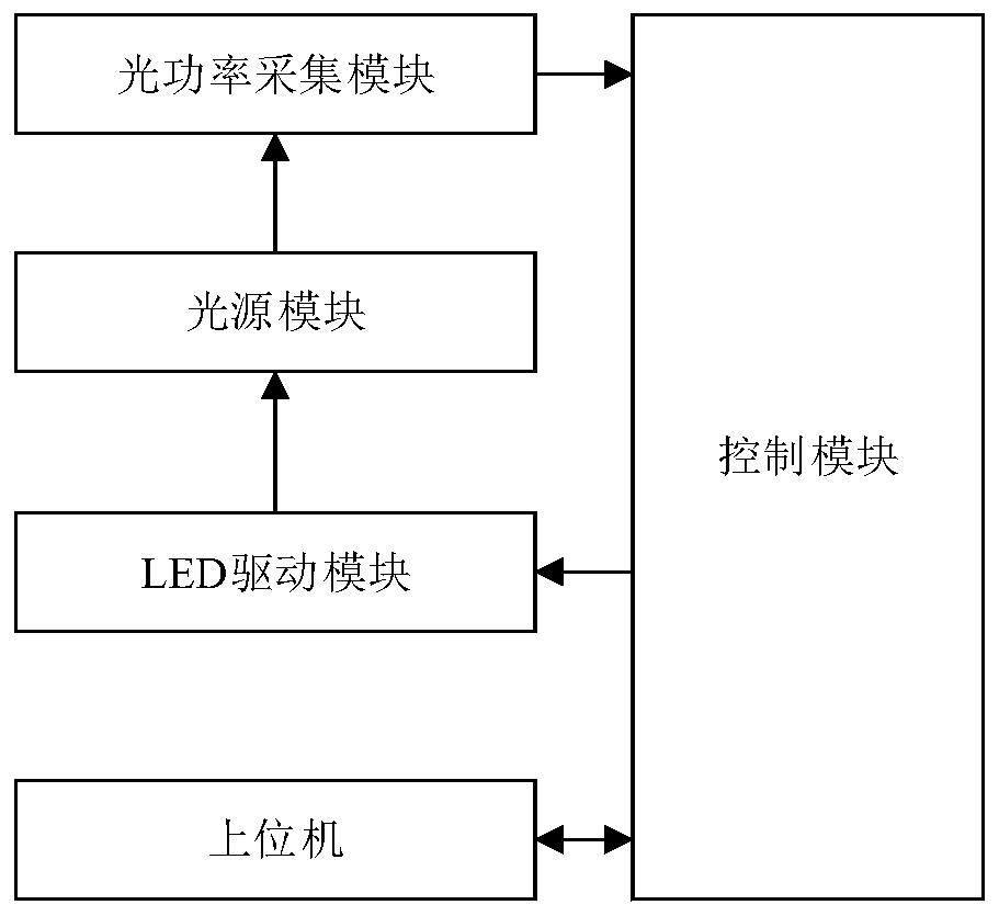
[0033] figure 1 It is a schematic structural diagram of an LED pulse excitation light source system according to an embodiment of the present invention.

[0034] Such as figure 1 As shown, the LED pulse excitation light source system of the present invention includes a host computer, a control module, an LED driver module and an optical power collection module. The control module is respectively connected with the upper computer, the LED driver module and the optical power acquisition module, the LED driver module is connected with the light source module, and the light source module is connected with the optical power acquisition module.

[0035] Specifically, the user sets the target LED pulse excitation light source ...


PUM


Abstract

The invention discloses an LED pulse excitation light source system. The LED pulse excitation light source system comprises an upper computer, a control module, an LED driving module, a light source module and an optical power acquisition module, wherein the upper computer is used for setting an optical power value of an LED pulse excitation light source, the control module is used for mapping theoptical power value of the LED pulse excitation light source to obtain a reference voltage signal value, the LED driving module is used for driving the light source module to emit light and adjustinga current required by the light source module according to the reference voltage signal value, the light source module is used for emitting light and outputting the LED pulse excitation light sourceat a special wave band, the optical power acquisition module is used for acquiring a coupling optical power value of the LED pulse excitation light source in real time, the control module is used forperforming closed-loop feedback and correction on the reference voltage signal value according to the coupling optical power value of the LED pulse excitation light source. By outputting the LED pulseexcitation light source at the special wave band and performing closed-loop feedback and correction on the reference voltage signal value, the optical power stability of the LED pulse excitation light source is achieved, and the problems of optical power and peak wavelength drift of the LED pulse excitation light source caused by environmental factors such as time and temperature are prevented, and the sensitivity and the stability of an underwater fluorescent sensor are improved.

Description

technical field [0001] The invention relates to the technical field of underwater fluorescence detection, in particular to an LED pulse excitation light source system. Background technique [0002] Today's marine pollution is becoming more and more serious, and underwater fluorescent sensors based on fluorescence detection methods are widely used in monitoring water quality parameters such as chlorophyll α, oil in water, and dissolved oxygen. In the fluorescence detection method, the fluorescence intensity is positively correlated with the intensity of the excitation light source, and is directly proportional under certain conditions. LED (Light Emitting Diode, Light Emitting Diode) is a commonly used excitation light source for underwater fluorescence sensors. The intensity and peak wavelength of the excitation light source determine the intensity and stability of fluorescence signals, and will directly affect the sensitivity and stability of underwater fluorescence sensors...

Claims


Application Information

Patent Timeline
Patent Type & Authority Applications(China)
IPC IPC(8): G01N21/64G01N21/01H05B33/08H05B44/00
CPCG01N21/6402G01N21/01Y02B20/30
Inventor 杨鹏吴国俊王东升宋矫健吕小鹏
Owner QINGDAO NAT LAB FOR MARINE SCI & TECH DEV CENT
Why Eureka
Try Eureka