Chemical-adding drip irrigation device for agriculture

A technology for dosing and agriculture, applied in agriculture, watering devices, devices for capturing or killing insects, etc., can solve the problems of increasing artificial planting costs, no dosing equipment, and large water source pollution, and prevent drip irrigation from being too fast. , liberate manpower and speed up the effect of mixing efficiency

Pending Publication Date: 2020-01-10
康浩东
View PDF8 Cites 8 Cited by
  • Summary
  • Abstract
  • Description
  • Claims
  • Application Information

AI Technical Summary

Problems solved by technology

[0003] The purpose of the present invention is to solve the problem of large water source pollution in the prior art, so it is easy to scale and block the dropper. The need for additional application of pesticides to the land undoubtedly increases the disadvantages of artificial planting costs, and a proposed agricultural drip irrigation device

Method used


Image

  • Chemical-adding drip irrigation device for agriculture
  • Chemical-adding drip irrigation device for agriculture
  • Chemical-adding drip irrigation device for agriculture

Examples


Embodiment 1

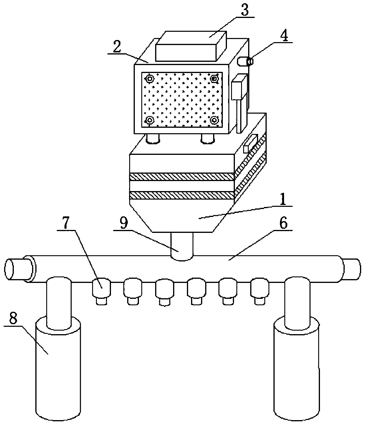
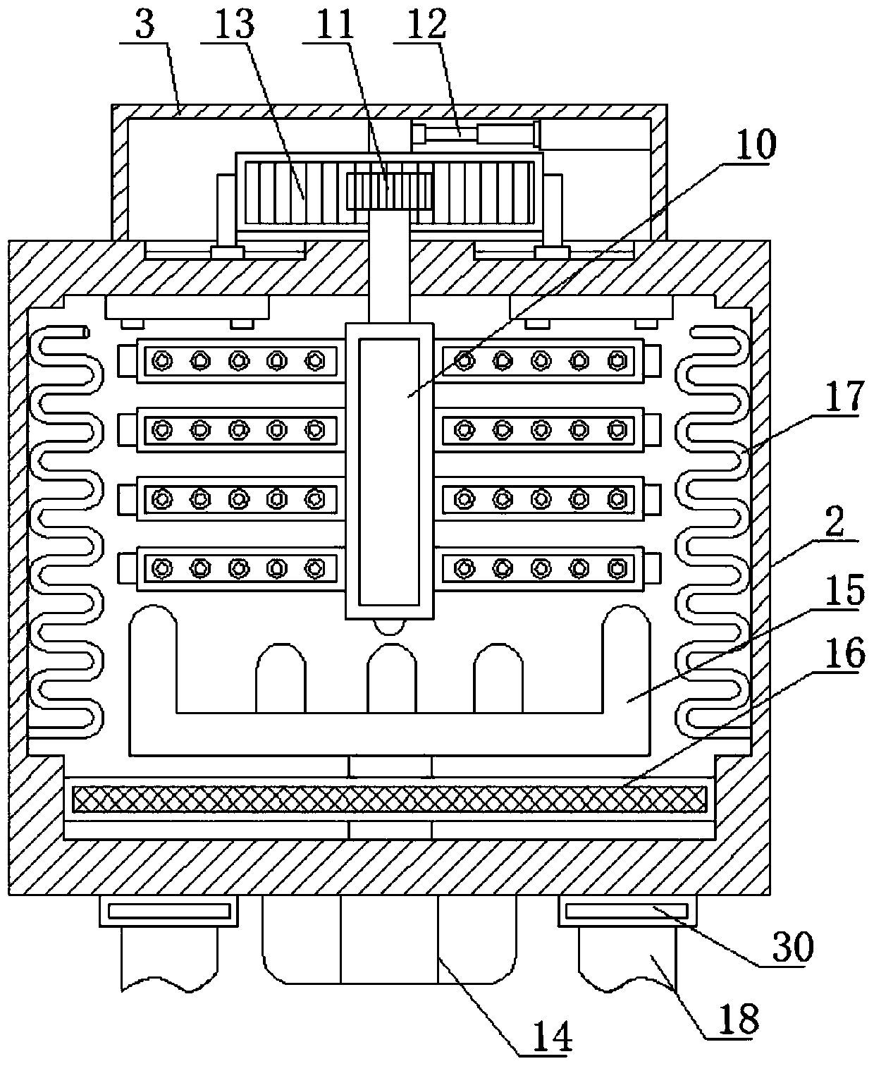
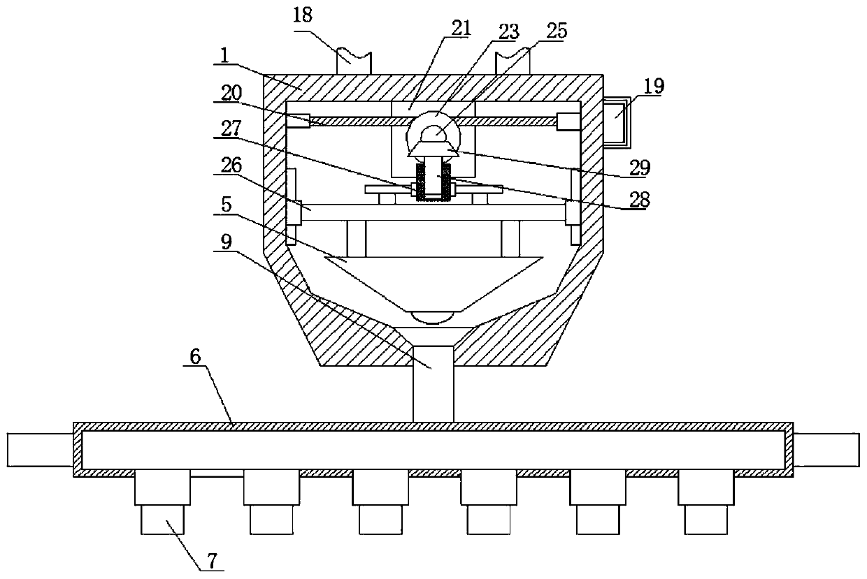
[0030] refer to Figure 1-5 , an agricultural drip irrigation device for adding medicine, comprising a flow limiting box 1, a mixing box 2 is fixedly connected to the top of the flow limiting box 1, and a connected liquid outlet pipe 9 is fixedly connected to the bottom of the flow limiting box 1, and the liquid outlet pipe 9 The bottom of the dropper 6 is fixedly connected with a connected dropper 6, and the top of the dropper 6 is fixedly connected with two symmetrically arranged support rods 8. The bottom of the dropper 6 is provided with a plurality of connected droppers 7, and one side of the mixing box 2 There is a connected dosing pipe 4 fixedly connected, a stirring shaft 10 is arranged in the mixing box 2, the top of the stirring shaft 10 extends into the power box 3 and is fixedly connected with a power assembly, the bottom inner wall of the mixing box 2 is fixedly connected with a disturbing The heating assembly is fixedly connected to the side wall of the mixing bo...

Embodiment 2

[0032] Further improved on the basis of embodiment one:

[0033]The power assembly includes a rack 13 slidingly installed in the power box 3, the top of the stirring shaft 10 extends into the mixing box 2 and is fixedly connected with a gear 11, and the gear 11 and the rack 13 are meshed, and the power box 3 is fixedly connected with Telescopic cylinder 12, the piston rod of telescopic cylinder 12 is fixedly connected to one side of rack 13. When the power assembly is used to drive the stirring shaft 10 to rotate, the telescopic cylinder 12 can be activated to push the rack 13 to perform lateral reciprocating motion, and the gear 11 is meshed with the rack 13, so it can drive the stirring shaft 10 to carry out positive and negative rotation, and then utilize the stirring shaft 10 to fully mix the medicinal solution and water added to the mixing tank 2.

[0034] The spoiler assembly includes a rotary motor 14 fixedly installed at the bottom of the mixing box 2, the output shaft...


PUM


Abstract

The invention belongs to the technical field of drip irrigation, particularly relates to a chemical-adding drip irrigation device for agriculture, and aims to solve the problems that an existing dripirrigation device is prone to scaling and drip pipe blocking, additional chemical application to land is needed, and artificial planting cost is increased. According to the technical scheme, the chemical-adding drip irrigation device comprises a flow limit tank and is characterized in that a mixing tank is fixedly connected above the flow limit tank, a liquid outlet pipe is fixedly connected to the bottom of the flow limit tank in a communicated manner, a drip pipe is fixedly connected to the bottom of the liquid outlet pipe in a communicated manner, two symmetrically-arranged support rods arefixedly connected to the top of the drip pipe, a plurality of drip ports are arranged at the bottom of the drip pipe in a communicated manner, and a chemical adding pipe is fixedly connected to one side of the mixing tank in a communicated manner. The chemical-adding drip irrigation device has the advantages that the device is simple in structural design and capable of achieving chemical adding,chemicals can be applied to crops during drip irrigation, manpower is liberated, impurities in water can be filtered, and drip pipe blocking can be prevented.

Description

technical field [0001] The invention relates to the technical field of drip irrigation, in particular to an agricultural medicine adding drip irrigation device. Background technique [0002] Drip irrigation is the use of plastic pipes to send water to the roots of crops through holes or drippers on capillaries with a diameter of about 10mm for local irrigation. It is currently the most effective water-saving irrigation method in arid and water-scarce areas, and the water utilization rate can reach 95%. Compared with sprinkler irrigation, drip irrigation has a higher effect of saving water and increasing production. At the same time, it can be combined with fertilization to more than double the fertilizer efficiency. It is suitable for irrigation of fruit trees, vegetables, commercial crops and greenhouses, and it can also be used for irrigation of field crops in places where there is drought and water shortage. Some drip tank equipment does not have corresponding dosing eq...

Claims


Application Information

Patent Timeline
Patent Type & Authority Applications(China)
IPC IPC(8): A01G25/02A01M17/00B01F7/18B01F15/06B01F15/00
CPCA01G25/02A01M17/002B01F27/191B01F27/90B01F35/332B01F35/187B01F35/93B01F2035/99Y02A40/22
Inventor 不公告发明人
Owner 康浩东
Why Eureka
Try Eureka