Suspension system with energy recovery device

An energy recovery device and suspension system technology, which is applied to power plants, jet propulsion devices, internal combustion propulsion devices, etc., can solve the problems of difficulty in popularization and utilization, no recovery, and reduced vibration energy recovery efficiency, so as to improve energy recovery and utilization. Efficiency, reducing energy loss, and facilitating post-maintenance effects

Pending Publication Date: 2020-01-10
IAT AUTOMOBILE TECH
View PDF1 Cites 0 Cited by
  • Summary
  • Abstract
  • Description
  • Claims
  • Application Information

AI Technical Summary

Problems solved by technology

The main function of the suspension system is to attenuate the vibration between the powertrain and the body or frame, and the energy of the vibration is not recovered, resulting in a waste of energy
In order to recover the vibration energy during driving, Wuhan University of Technology discloses a vane type energy recovery shock absorber in CN102926956A, in order not to produce reverse phenomenon, which adopts four one-way valves, and adopts a mechanical accumulator , airbag accumulator, etc., have complex structures, occupy a large space, and are difficult to popularize and utilize
CN1030099956A discloses an energy storage suspension device with vibration energy recovery, in which energy recovery is realized by means of spring transmission, and three check valves are used, which not only reduces the recovery efficiency of vibration energy, but also has a relatively Complicated, where the hydraulic cylinder is directly located between the body and the wheel (i.e., the sprung mass and the unsprung mass), which has been verified to cause large vibrations in the X and Y directions of the hydraulic cylinder, and the reliability of the system is also poor

Method used


Image

  • Suspension system with energy recovery device
  • Suspension system with energy recovery device
  • Suspension system with energy recovery device

Examples


Embodiment 1

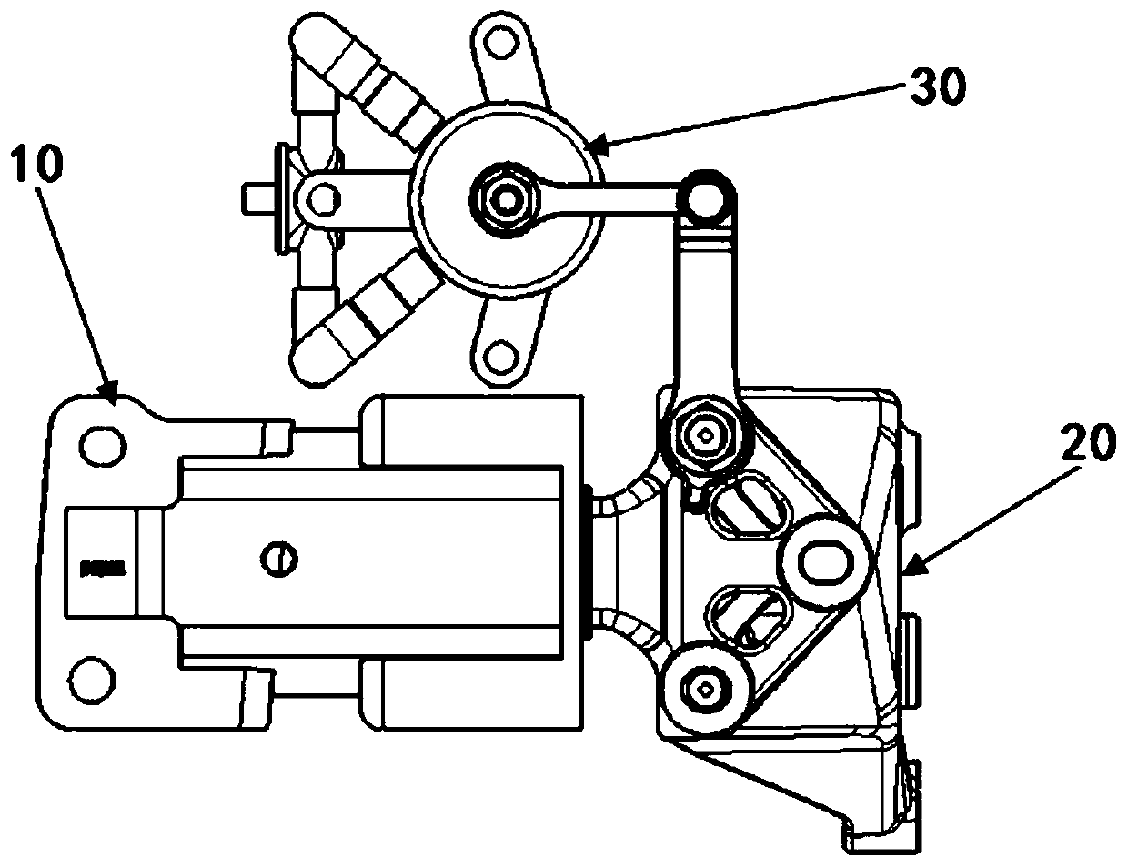
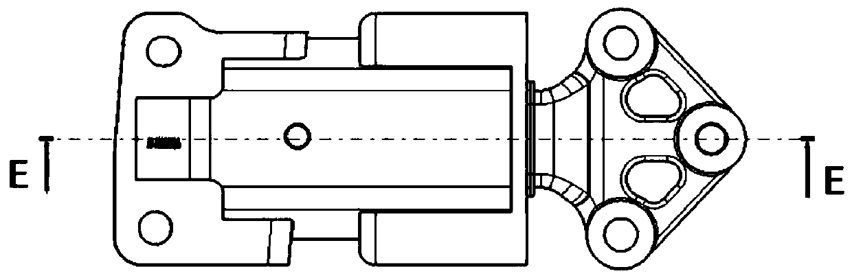
[0036] In order to convert the irregular motion of the power assembly into one-way reciprocating motion, reduce vibration and noise, perform energy recovery, and reduce energy waste, this embodiment provides a method such as Figure 2-14 The suspension system shown includes a suspension cushion 10 and a suspension bracket 20, the suspension cushion 10 is arranged on the powertrain (not shown in the figure), and the suspension bracket 20 is connected with the suspension bracket 20 The suspension cushion 10 is connected, and the suspension bracket 20 is provided with an energy recovery device 30 .

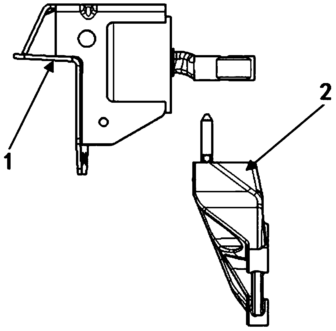
[0037] like Figure 3-4 As shown, the suspension cushion 10 includes an upper bracket 13 and a lower bracket 11, an outer casing 12 is arranged between the upper bracket 13 and the lower bracket 11, and a horizontal bracket 16 is arranged in the middle of the outer casing 12, The outer end of the horizontal support 16 protrudes from the outer casing 12, and the inner end of the hori...


PUM


Abstract

The invention relates to a suspension system with an energy recovery device, and belongs to the field of automobile designing and manufacturing. The suspension system with the energy recovery device comprises a suspension cushion and a suspension bracket; the suspension bracket is provided with an energy recovery device, and the energy recovery device is composed of a ball pin mechanism, a hydraulic device, a turbine mechanism and a one-way valve; the hydraulic device comprises a barrel body which is internally provided with a piston, and a rod body of the piston is arranged in the Z direction; the outer wall of the barrel body is provided with a first pipeline and a second pipeline which communicate with the interior of the barrel body; the turbine mechanism is arranged between the middles of the first pipeline and the second pipeline, and the lower end of the second pipeline is provided with the one-way valve; and one end of the ball pin mechanism is connected with the suspension bracket, and the other end of the ball pin mechanism is connected with a rod body of a piston rod. According to the suspension system provided by the invention, irrgular movement is converted into Z-direction movement, the energy recovery and utilization efficiency is improved, in addition, X-direction vibration and Y-direction vibration of the energy recovery device are reduced, and the reliabilityof the suspension system is improved.

Description

technical field [0001] The present invention relates to automobile design and manufacture, and more particularly, the present invention relates to a suspension system with an energy recovery device. Background technique [0002] figure 1 The structure of the suspension system without energy recovery device in the prior art is shown, which is mainly composed of a suspension cushion assembly 1 and a suspension bracket 2 . The main function of the suspension system is to attenuate the vibration between the powertrain and the body or frame. The energy of the vibration is not recovered, resulting in a waste of energy. In order to recover the vibration energy during driving, Wuhan University of Technology discloses a vane type energy recovery shock absorber in CN102926956A, in order not to produce reverse phenomenon, which adopts four one-way valves, and adopts a mechanical accumulator , air bag type accumulator etc., the structure is complicated, and it takes up a lot of space,...

Claims


Application Information

Patent Timeline
IPC IPC(8): B60K5/12F03G7/08
CPCB60K5/12F03G7/08
Inventor 何超
Owner IAT AUTOMOBILE TECH
Why Eureka
Try Eureka