
Overhead floor heating mounting structure of fabricated ground

An installation structure and assembly technology, applied in the direction of floor, heating method, building structure, etc., can solve the problems of prolonged construction period, long construction period, dust pollution, etc., and achieve the effect of improving overall bearing performance, simple installation and shortening construction period.

Pending Publication Date: 2020-01-10
GOLD MANTIS FINE DECORATION TECH SUZHOU CO LTD
View PDF0 Cites 5 Cited by
  • Summary
  • Abstract
  • Description
  • Claims
  • Application Information

AI Technical Summary

Problems solved by technology

However, for floors with stone and ceramic tiles, there is still no better dry construction method for floor heating modules, and only traditional wet construction methods can be used, which has the following disadvantages: 1. Many processes and long construction period: the wet construction of traditional tiles or floors The standard process of operation and construction is complex and indispensable, requiring multiple processes to complete, and some processes in the wet work method involve natural drying, which prolongs the construction period; 2. Serious pollution: a large amount of cement is used in the traditional wet work method Mortar, on-site dust pollution is serious and prone to messy situations; 3. Difficulty in later pipeline maintenance: The traditional tile and floor paving process adopts wet paving, and the pipeline is directly buried in the cement filling layer. Later maintenance requires tiles or floors, It is very troublesome to smash the cement filling layer

Method used


Image

  • Overhead floor heating mounting structure of fabricated ground
  • Overhead floor heating mounting structure of fabricated ground
  • Overhead floor heating mounting structure of fabricated ground

Examples


Embodiment 1

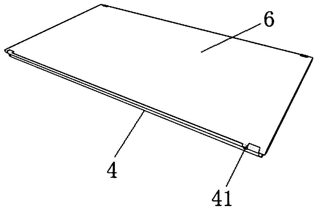
[0035] see Figure 1 to Figure 5 , the figure shows a prefabricated ground overhead floor heating installation structure provided by Embodiment 1 of the present invention, which includes: a frame assembly, which includes a keel 1, a connecting leveling member 2 and a base plate 3, and the keel 1 is leveled by connecting The parts 2 are connected to each other to form a plurality of connected frame units. The base plate 3 is arranged on the keel 1, and one frame unit corresponds to one base plate 3, and the surroundings of the base plate 3 correspond to four keel 1s; the floor heating component includes multiple mutual The spliced ​​floor heating unit, the floor heating unit includes a cladding board 4, a thermal insulation board 5, and a balance board 6 arranged sequentially from bottom to bottom, and the edge of the cladding board 4 covers the edges of the thermal insulation board 5 and the balance board 6; the inside of the thermal insulation board 5 A pipeline channel 51 is...

Embodiment 2

[0045] see Figure 5 to Figure 8 , the figure shows a prefabricated ground overhead floor heating installation structure provided by Embodiment 2 of the present invention. This embodiment further makes the following technical solutions as improvements on the basis of the above-mentioned embodiments: connection adjustment The flat part 2 includes a bearing platform 21, a connecting plate 22 arranged on the side of the bearing platform 21, a connecting platform 23 arranged on the bearing platform 21, and an adjusting screw 24. The connecting platform 23 protrudes from the bearing platform 21, and the adjusting screw 24 threads Connect the center of the bearing platform 21 and the connecting platform 23, and the adjusting screw 24 is located at the bottom of the bearing platform 21; the end of the keel 1 is sleeved on the connecting plate 22 and docked with the end of the connecting platform 23; the end of the keel 1 It is in the shape of "convex"; the connection table 23 is in t...

Embodiment 3

[0047] see Figure 7 , the figure shows a prefabricated ground overhead floor heating installation structure provided by Embodiment 3 of the present invention. On the basis of the above-mentioned embodiments, this embodiment further makes the following technical solutions as improvements: carrying platform 21 and the center of the connection table 23 are provided with an adjustment hole 25, and the adjustment screw rod 24 is threadedly connected to the adjustment hole 25, and the adjustment hole 25 is a through hole; the top of the adjustment screw rod 24 is provided with a "one" word groove 241; Including a support pad 26, the support pad 26 is arranged at the bottom of the adjusting screw 24, and the support pad 26 is circular. Through the setting of the above structure, the "one" groove is exposed on the top of the adjustment hole 25, and the adjustment screw 24 can be rotated through the "one" groove 241 on the top to achieve the purpose of adjustment; the support pad 26 n...


PUM


Abstract

The invention provides an overhead floor heating mounting structure of the fabricated ground. The structure comprises a frame assembly and a floor heating assembly. The frame assembly comprises keels,connecting leveling parts and base plates. The keels are connected through the connecting leveling parts, multiple connected frame units are formed, the base plates are arranged on the keels, one frame unit corresponds to one base plate, and the peripheries of the base plates correspond to the four keels. The floor heating assembly comprises multiple spliced floor heating units. The floor heatingunits comprise cladding plates, heat insulating plates and balancing plates, all of which are sequentially arranged from bottom to top, and the edges of the heat insulating plates and the edges of the balancing plates are coated with the edges of the cladding plates. Pipeline passageways are formed in the heat insulating plates. Connectors are formed in the side faces of the cladding plates. Thefloor heating units are arranged on the frame assembly. Compared with the prior art, the overhead floor heating mounting structure has the following beneficial effects that a dry method construction method is adopted, construction is rapid, convenient, environmentally friendly and free of pollution, meanwhile, the construction efficiency and the construction quality are improved, and later maintenance is facilitated.

Description

technical field [0001] The invention relates to an installation structure for overhead floor heating on the ground, in particular to an installation structure for overhead floor heating on the assembled floor. Background technique [0002] Prefabricated decoration is a new form of decoration construction in recent years. As the name implies, prefabricated decoration is to complete the production of various parts and components required for decoration in the factory, and then transport them to the decoration site for assembly and installation, eliminating the need for traditional decoration on-site measurement and cutting of various parts and components. The construction is simpler and more convenient, which can greatly improve the construction efficiency of the decoration site, and the construction site is more tidy and beautiful, and will not produce too much decoration material waste. It is a more green and environmentally friendly form of decoration construction. [0003...

Claims


Application Information

Patent Timeline
Patent Type & Authority Applications(China)
IPC IPC(8): E04F15/024E04F15/18F24D3/14
CPCE04F15/024E04F15/02405E04F15/02452E04F15/02458E04F15/0247E04F15/18E04F2290/023E04F2290/04F24D3/149
Inventor 陈莹王浦东佘予然
Owner GOLD MANTIS FINE DECORATION TECH SUZHOU CO LTD
Learn More