
Automatic variable-displacement walking motor assembly, hydraulic driving walking control system and application thereof

A travel motor, automatic variable technology, applied in transmission control, fluid pressure actuation system components, servo motors, etc., can solve problems such as poor operating comfort, sudden braking, and non-compliance with driving operation requirements.

Pending Publication Date: 2020-01-10
FUJIAN JINGONG MACHINERY
View PDF0 Cites 0 Cited by
  • Summary
  • Abstract
  • Description
  • Claims
  • Application Information

AI Technical Summary

Problems solved by technology

However, when the whole machine stops, the foot pilot valve is released, and the hydraulic control reversing valve quickly returns to the neutral position. The whole machine only relies on the buffer valve inside the travel motor for buffering, which will cause sudden braking, poor operating comfort, and does not meet the driving operation requirements.
[0004] Therefore, the walking control of the existing fully hydraulically driven walking equipment meets the driving operation requirements when starting, but the sudden stop feeling is strong and the comfort is poor

Method used


Image

  • Automatic variable-displacement walking motor assembly, hydraulic driving walking control system and application thereof
  • Automatic variable-displacement walking motor assembly, hydraulic driving walking control system and application thereof
  • Automatic variable-displacement walking motor assembly, hydraulic driving walking control system and application thereof

Examples


Embodiment Construction

[0023] Below in conjunction with specific embodiment, this case is described in further detail.

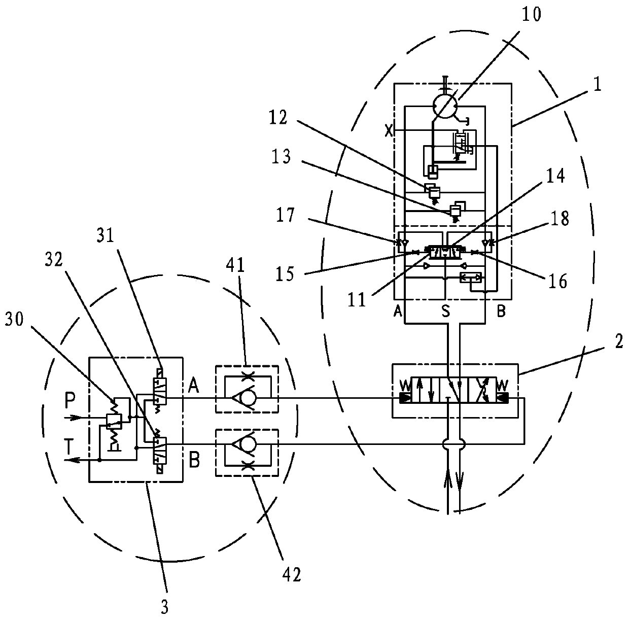
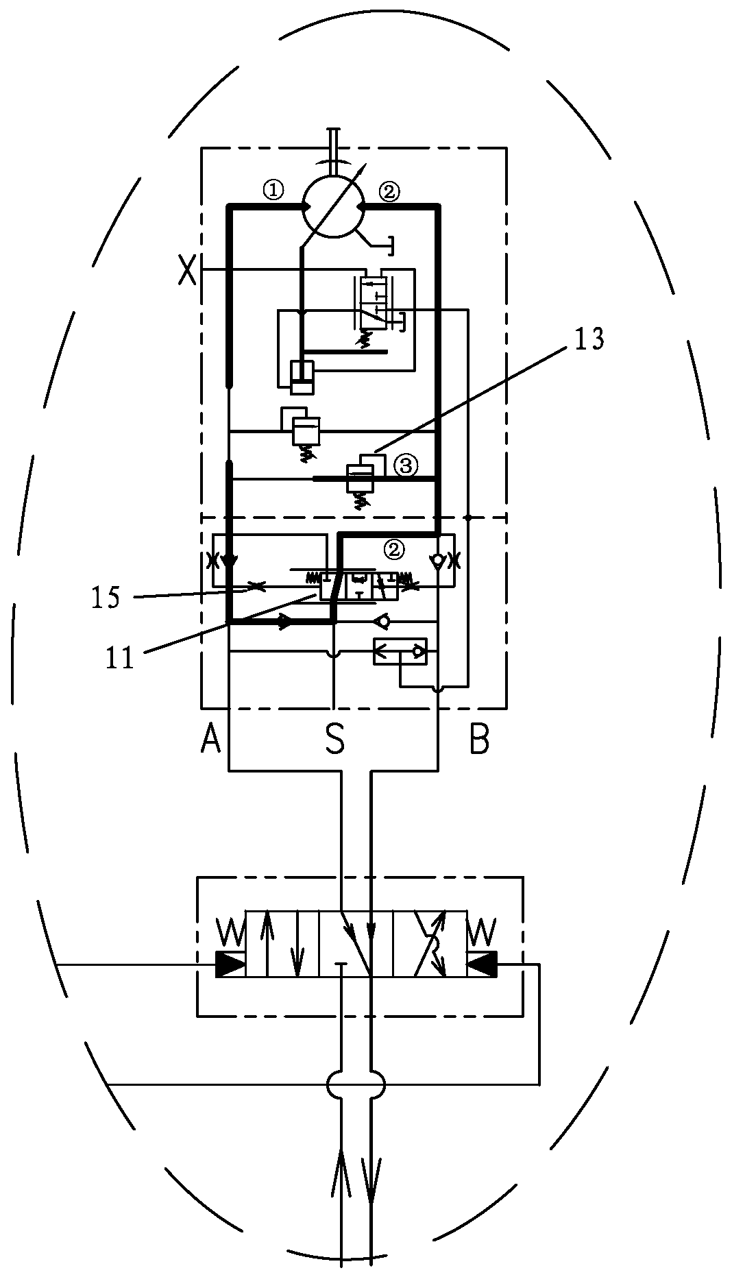
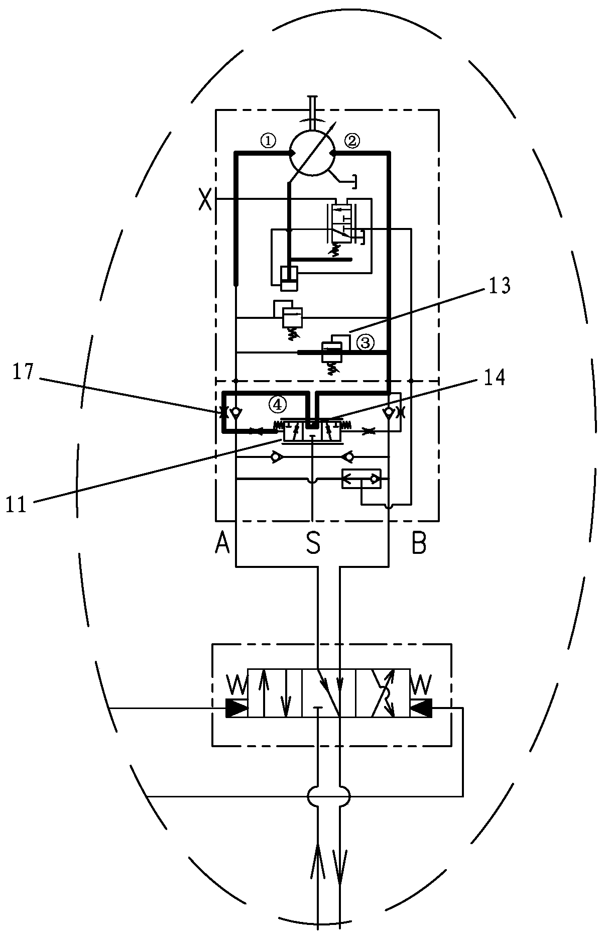
[0024] This case involves a hydraulic drive travel control system, such as Figure 1-3 As shown, the high-voltage automatic variable travel motor assembly 1 is adopted. The walking control system preferably also has a hydraulically controlled reversing valve 2 and a walking foot pilot valve 3, which are sequentially adapted and connected with the high-pressure automatic variable-variable walking motor assembly 1 to realize effective walking control. figure 1 , the left dotted circle corresponds to the pilot oil circuit, and the right dotted circle corresponds to the working oil circuit. The walking foot pilot valve 3 is provided with a pilot valve pedal 30, a forward switch 31 and a rear leg switch 32, and the working ports include an oil source port P and a fuel tank port T. The forward switch 31 and the rear leg switch 32 correspond to port A and port B respectively, and are c...


PUM


Abstract

The invention discloses an automatic variable-displacement walking motor assembly, a hydraulic driving walking control system and application thereof. The automatic variable-displacement walking motorassembly is provided with a variable-displacement motor, a balance valve, a left overflow valve and a right overflow valve. A left throttling opening and a right throttling opening are formed in theleft valve end and the right valve end of the balance valve respectively. A left one-way throttling valve is arranged on a corresponding left oil path between the left throttling opening and a left oil passing hole of the variable-displacement motor, and a right one-way throttling valve is arranged on a corresponding right oil path between the right throttling opening and a right oil passing holeof the variable-displacement motor. A middle throttling hole is additionally formed in the middle of the balance valve, and the left end and the right end of the middle throttling hole communicate with the throttling inlet end of the left one-way throttling valve and the throttling inlet end of the right one-way throttling valve respectively. According to the scheme, an innovative design is provided for an internal buffer structure of the automatic variable-displacement walking motor, so that the internal buffer of the motor is properly extended, the time that a high-speed driving state is switched to a parking state is effectively prolonged, the effect of relieving sudden stopping is effectively improved, and the operation comfort when a foot leaves a foot pilot valve pedal is improved.

Description

technical field [0001] The invention relates to a travel control system, in particular to an automatic variable travel motor assembly, a hydraulic drive travel control system and applications thereof. Background technique [0002] At present, the walking principle of the fully hydraulically driven walking equipment is that the gearbox is driven by the traveling motor. The gearbox itself has no distinction between forward and reverse, and only has two gears of high speed and low speed. The travel motor is a high-voltage automatic variable motor, that is, when the travel resistance is large, such as when starting or climbing a slope, the gearbox needs a larger drive torque input, and the motor works in a state of large displacement. When the travel resistance becomes smaller, the travel motor responds accordingly. Automatic adjustment works in the state of small displacement. [0003] In terms of operation, start the engine at idle speed, put forward (reverse) gear first, ste...

Claims


Application Information

Patent Timeline
IPC IPC(8): F16H61/64F16H41/00F15B15/22F15B21/00F15B13/04F15B11/08
CPCF16H61/64F16H41/00F15B15/22F15B21/001F15B13/0401F15B11/08
Inventor 吕志忠吴景毅赵家宏肖传奇刘雄伟李景灿
Owner FUJIAN JINGONG MACHINERY
Learn More