Cloth defect detection device and real-time detection method

A detection device and cloth technology, applied in the direction of measuring devices, optical testing flaws/defects, complex mathematical operations, etc., can solve problems such as insufficient reliability, long distance, uncontrollable defect range, etc.

Active Publication Date: 2020-01-10
HANGZHOU LIPO SCI & TECH
View PDF10 Cites 1 Cited by
  • Summary
  • Abstract
  • Description
  • Claims
  • Application Information

AI Technical Summary

Problems solved by technology

For this detection method, it relies on the fluttering of the yarn, which has insufficient probability and reliability. When the fluttering yarn does not pass through the equipment, it cannot be detected. For example, the

Method used


Image

  • Cloth defect detection device and real-time detection method
  • Cloth defect detection device and real-time detection method
  • Cloth defect detection device and real-time detection method

Examples


Embodiment 1

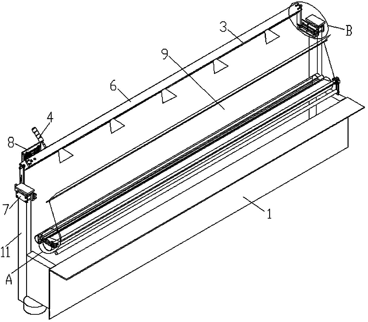
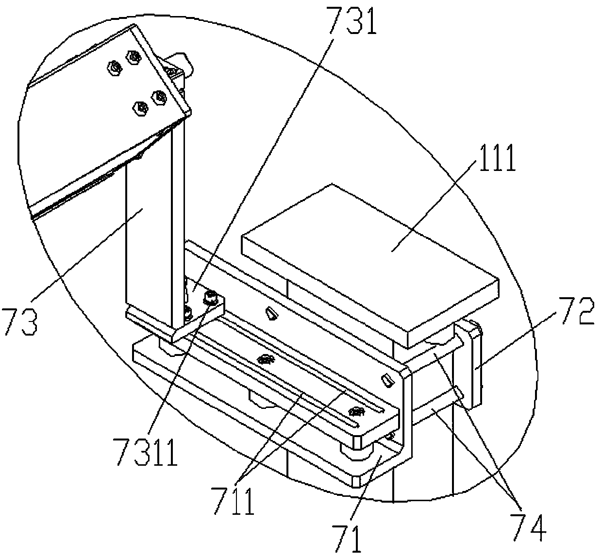
[0090] Such as Figure 1-4 As shown, a cloth defect detection device described in this embodiment includes a background component provided on the warp knitting machine 1 for providing a background for the cloth to be detected, and a light source for illuminating the cloth to be detected to provide light for the cloth. The component is used to photograph the cloth to be detected to collect the camera component of the cloth image and the main control device connected to the camera component.

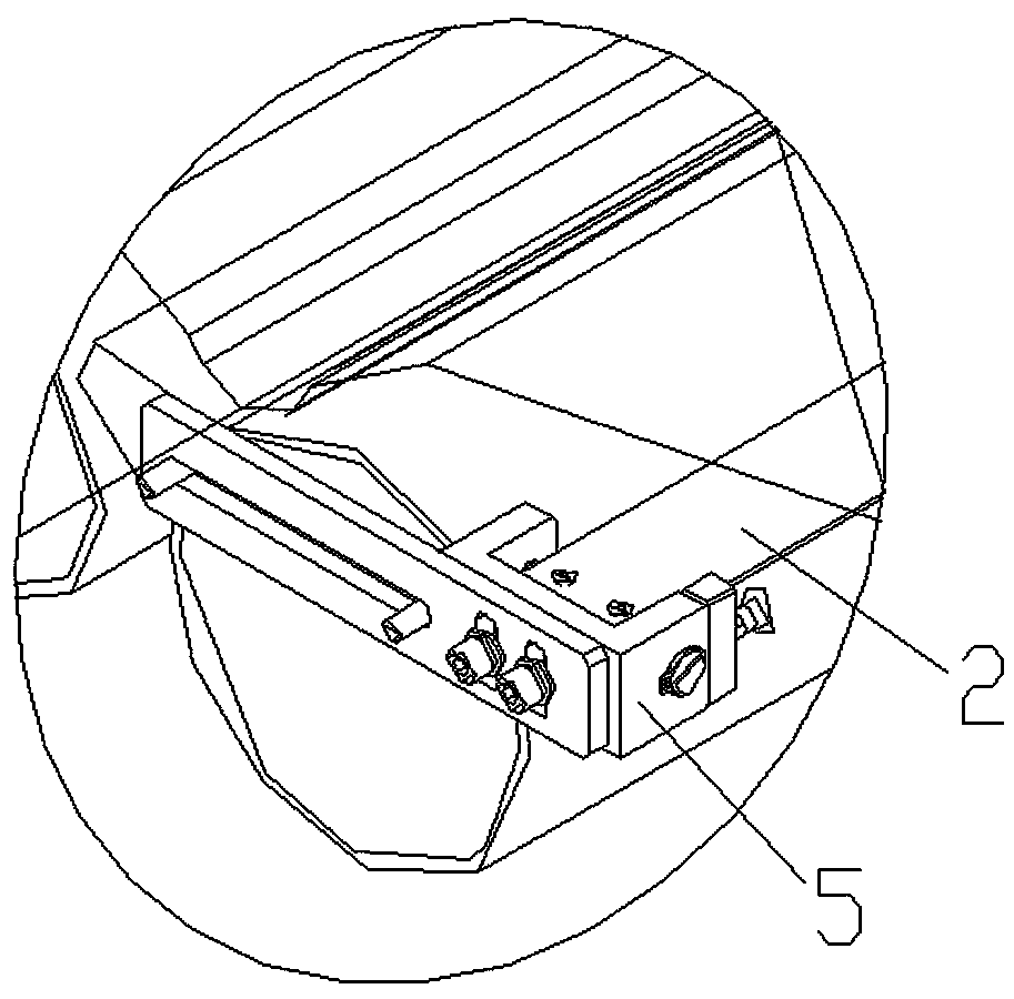
[0091] In this embodiment, the background assembly includes a background board 2 and a background board bracket 5, and the two ends of the background board 2 are respectively fixed on the warp knitting machine 1 through the background board bracket 5, and the length of the background board 2 is not less than the The width of the cloth 9 is to ensure that the cloth to be detected is in the background range provided by the background board 2 in the width direction, and the width of the backg...

Embodiment 2

[0097] A method for real-time detection of cloth defects described in this embodiment mainly includes two steps:

[0098] Step S1, collect several pictures and use the mixed Gaussian model for background modeling, obtain a defect segmentation map, and calculate the framing position in the image at the same time. Among them, the mixed Gaussian model can learn all kinds of different styles of cloth and establish its background model, so as to achieve defect segmentation; the framing positioning algorithm can automatically calculate the framing position of the cloth, which greatly simplifies the operation difficulty of the on-site workers after changing the cloth.

[0099] Further, in the step S1, the background modeling specifically includes the following:

[0100]S111. Model initialization , for the first Each pixel of an image Build a Gaussian model:

[0101] (1)

[0102] in, Indicates the first Gaussian model, , , , , it's all about The function, Re...


PUM


Abstract

The invention discloses a cloth defect detection device. The device comprises a background assembly, a light source assembly, a camera assembly and a main control device; the background assembly is arranged on a warp knitting machine and used for providing a background for to-be-detected cloth; the light source assembly is used for irradiating the to-be-detected cloth to provide illumination for the cloth; the camera assembly is used for shooting the to-be-detected cloth to acquire cloth images; the main control device is connected with the camera assembly; a background plate is arranged belowthe to-be-detected cloth; a linear light source is arranged above the to-be-detected cloth along the width direction of the cloth and irradiates the overlapped area of the to-be-detected cloth and the background plate; an industrial camera is arranged above the to-be-detected cloth; the lens of the industrial camera points to the intersection area of the irradiation light of the linear light source and the to-be-detected cloth; a distance L1 from the lens of the industrial camera to the intersection area of the irradiation light of the linear light source and the to-be-detected cloth is 800-1000 mm; and the an angle alpha between the axis of the lens of the industrial camera and a plane where the to-be-detected cloth is located is 55-75 degrees. The device can accurately detect defects onthe surface of cloth and give alarms, and is simple in structure and good in practicability.

Description

technical field [0001] The invention relates to the technical field of cloth detection, in particular to a cloth defect detection device and a real-time detection method. Background technique [0002] The cloth produced by the high-speed warp knitting machine is a kind of gray cloth with a wide range of applications, and it is widely used in the fields of window screens, sweaters, and carvings. In the cloth production process, due to multiple factors such as equipment stability, process arrangement, and thread quality, defects such as broken yarns, parallel lines, and holes will appear on the cloth surface. These defects will reduce the quality of the product and increase the work of the on-site employees. The quantity reduces the effective production time of the equipment and reduces the profit margin. [0003] At present, the traditional control method in the textile industry is to use manual inspection, which is inefficient, difficult to employ, and unsatisfactory for qu...

Claims


Application Information

Patent Timeline
IPC IPC(8): G01N21/95G01N21/88G06F17/15
CPCG01N21/8851G01N21/95G01N2021/8861G01N2021/8887G06F17/15
Inventor 胡娜任涛涛林帅邓邹超吕辉
Owner HANGZHOU LIPO SCI & TECH
Why Eureka
Try Eureka