Transformer district tail end sensing system and method

A technology of perception system and station area, which is applied in the direction of measuring devices, instruments, measuring electricity, etc., can solve the problems of insufficient power quality data collection and analysis capabilities at the end of the power grid, low level of accident responsibility identification, and poor real-time performance, so as to reduce end management. Cost, improvement of power quality level, and the effect of preventing electricity theft

Active Publication Date: 2020-01-10
FIBRLINK NETWORKS +1
View PDF13 Cites 12 Cited by
  • Summary
  • Abstract
  • Description
  • Claims
  • Application Information

AI Technical Summary

Problems solved by technology

The technical level of power outage fault handling in residential areas is still in the passive repair stage, and there are still problems such as inaccurate positioning and low level of accident responsibility identification; (2) The state perception level of the power grid in the station area is low, and the coverage of power quality monitoring equipment is limited. Poor real-time performance, insufficient ability to collect and analyze power quality data at the end of the grid (incoming lines of residential users), common problems such as unbalanced three-phase, high load rate, low voltage, excessive reactive power, etc., and lack of intelligent data analysis ; (3) Residential users have a low level of perception of power consumption status, and the existing technology has not deeply explored the value of fine-grained power consumption behavior data, and has not realized the identification of user power consumption load

Method used


Image

  • Transformer district tail end sensing system and method
  • Transformer district tail end sensing system and method
  • Transformer district tail end sensing system and method

Examples


Embodiment Construction

[0052] In order to make the object, technical solution and advantages of the present invention clearer, the present invention will be described in further detail below in conjunction with specific embodiments and with reference to the accompanying drawings.

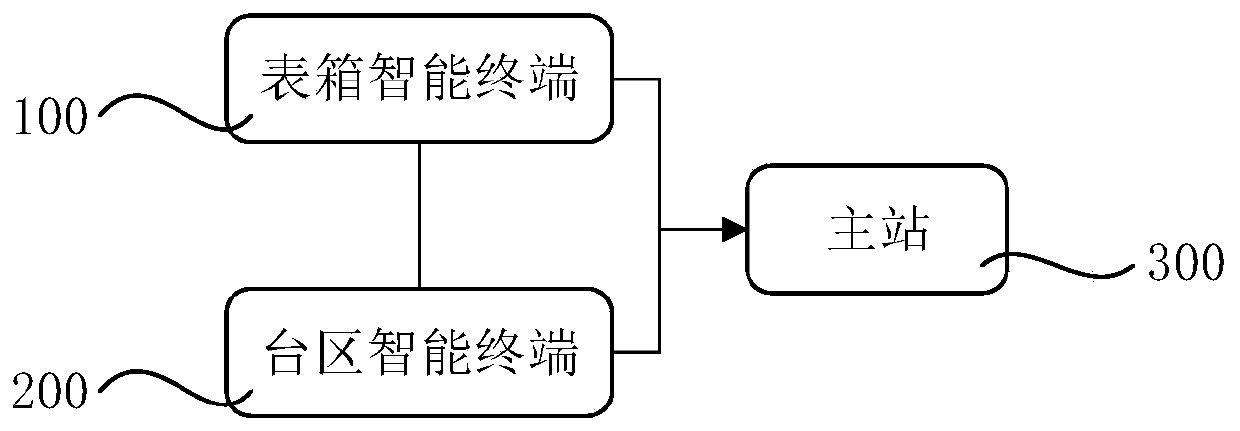
[0053] Such as figure 1 As shown in the figure, it is a schematic diagram of the structure of the terminal perception system of the station area according to the embodiment of the present invention, including the meter box intelligent terminal 100 , the station area intelligent terminal 200 and the master station 300 .

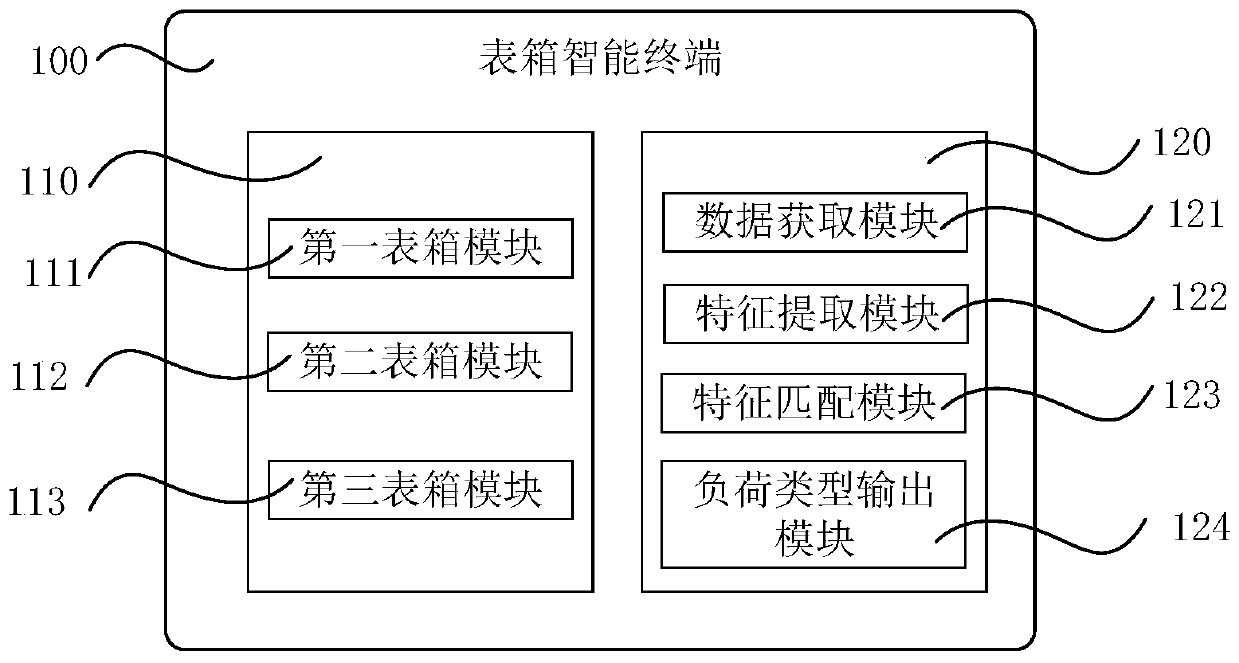
[0054] Among them, the meter box intelligent terminal 100 is used to monitor the user terminal, and determine the cause of the meter box power failure and identify the user load type, and send the power failure reason and user load type to the master station 300;

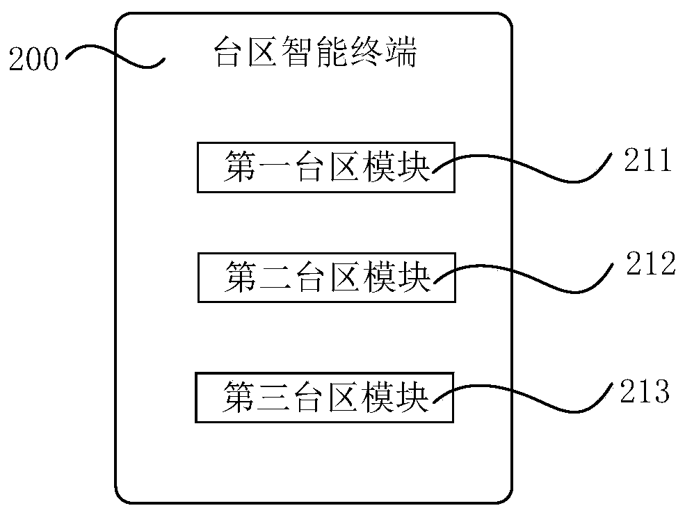
[0055] The station area intelligent terminal 200 is installed on the side of the transformer outlet cabinet, and is used to monitor the meter ...


PUM


Abstract

The invention discloses a transformer district tail end sensing system which comprises a meter box intelligent terminal which is used for monitoring a user end, determining a meter box power failure reason and identifying a user load type, and transmitting the power failure reason and the user load type to a master station, a transformer district intelligent terminal which is installed on one sideof a transformer outgoing line cabinet and is used for monitoring the meter box intelligent terminal and a transformer district, judging transformer district fault information and sending the fault information to the master station, and the master station which is used for receiving the power failure reason and the user load type sent by the meter box intelligent terminal and receiving the faultinformation sent by the transformer district intelligent terminal. According to the invention, two layers of intelligent terminal equipment are adopted to acquire fine-grained power utilization characteristic data, the functions of automatic identification of transformer district topology, transformer district fault positioning and responsibility definition, non-intrusive load identification of users and the like are realized through characteristic identification and a big data algorithm, and the management level of a low-voltage transformer district and a user experience are comprehensively improved.

Description

technical field [0001] The invention relates to the field of smart grid and smart electricity utilization, in particular to a station terminal sensing system and method. Background technique [0002] With the development of smart grids, the growth rate of residents' electricity consumption is accelerating, and there are now problems such as a large number of residential electricity users, complex electricity consumption behaviors, difficult fault location, and low level of grid monitoring, including the following aspects: [0003] (1) The level of active perception of faults in residential station areas is low, and the troubleshooting time is long. The technical level of power outage fault handling in residential areas is still in the passive repair stage, and there are still problems such as inaccurate positioning and low level of accident responsibility identification; (2) The state perception level of the power grid in the station area is low, and the coverage of power qu...

Claims


Application Information

Patent Timeline
IPC IPC(8): G01R35/04G01R22/06G01R31/50
CPCG01R35/04G01R22/06G01R22/068
Inventor 王卫卫李博赵静王奔刁琪
Owner FIBRLINK NETWORKS
Why Eureka
Try Eureka