
Thick film power hybrid integrated circuit

A hybrid integrated circuit and power technology, applied in circuits, electrical components, electric solid devices, etc., can solve the problems of reducing the heat dissipation area of ​​the power chip, unfavorable power chip heat, and unfavorable rapid heat conduction of the chip, etc., to increase the effective welding area and Heat dissipation area, improve heat capacity and heat dissipation performance, eliminate the effect of solder interface voids

Active Publication Date: 2020-01-10
EAST CHINA INST OF OPTOELECTRONICS INTEGRATEDDEVICE
View PDF7 Cites 2 Cited by
  • Summary
  • Abstract
  • Description
  • Claims
  • Application Information

AI Technical Summary

Problems solved by technology

Although the heat dissipation capacity of copper is obviously better than that of Kovar, 10# steel and other materials, the thermal expansion coefficient of copper is quite different from that of ceramic substrates. When the size of the base of the housing and the base is large, there will be a thermal mismatch between the base and the base of the housing. problems, which in turn lead to chipping of the substrate, making it inconvenient to use copper housing base material as a whole
At the same time, whether it is a copper shell base or a copper alloy shell base, its weight is obviously too large. The overall use of a copper shell base or a copper alloy shell base is not conducive to lightweight and miniaturized integration, and the pins of this type of shell base are sintered with the shell. It is very difficult to realize the hermetic packaging process, and the cost of the shell will increase significantly. Therefore, the base of the power hybrid integrated circuit shell is mostly made of Kovar material or 10# steel material
[0004] At present, although the power chip is welded on the ceramic substrate or through the heat sink, there are still some problems in the heat dissipation performance of the current technical method. First, the heat sink is thin and the heat capacity is small, which is not conducive to The heat of the power chip dissipates quickly, but if the thickness of the heat sink block is simply increased, it is bound to be limited by the height and size of the circuit; second, the thermal conductivity of the base material of the metal case corresponding to the power chip is not too high, which is not conducive to the heat dissipation of larger power chips. Dissipate quickly to the base of the shell and to the external environment, but if copper materials are used, for high-power chips (the area also increases) and large-area ceramics, under the action of temperature cycle and temperature shock thermal stress, the copper heat sink and power chip 1. The thermal mismatch between the ceramics will cause cracks on the chips and ceramics; thirdly, the heat of the power chips is dissipated downwards to achieve a radial feature, but the upper and lower surfaces of the heat sink are generally the same size (the bottom angle is at a right angle) , does not provide the corresponding radial structure settings, which affects the heat dissipation effect of the heat sink; Fourth, there are holes to a certain extent in the soldering interface between the chip and the heat sink. Fifth, the base of the power hybrid integrated circuit shell is designed as a conventional flat structure, and the heat dissipation area to the surrounding environment is very limited, which is not conducive to the heat dissipation of the entire power circuit to the surrounding environment

Method used


Image

  • Thick film power hybrid integrated circuit
  • Thick film power hybrid integrated circuit
  • Thick film power hybrid integrated circuit

Examples


Embodiment Construction

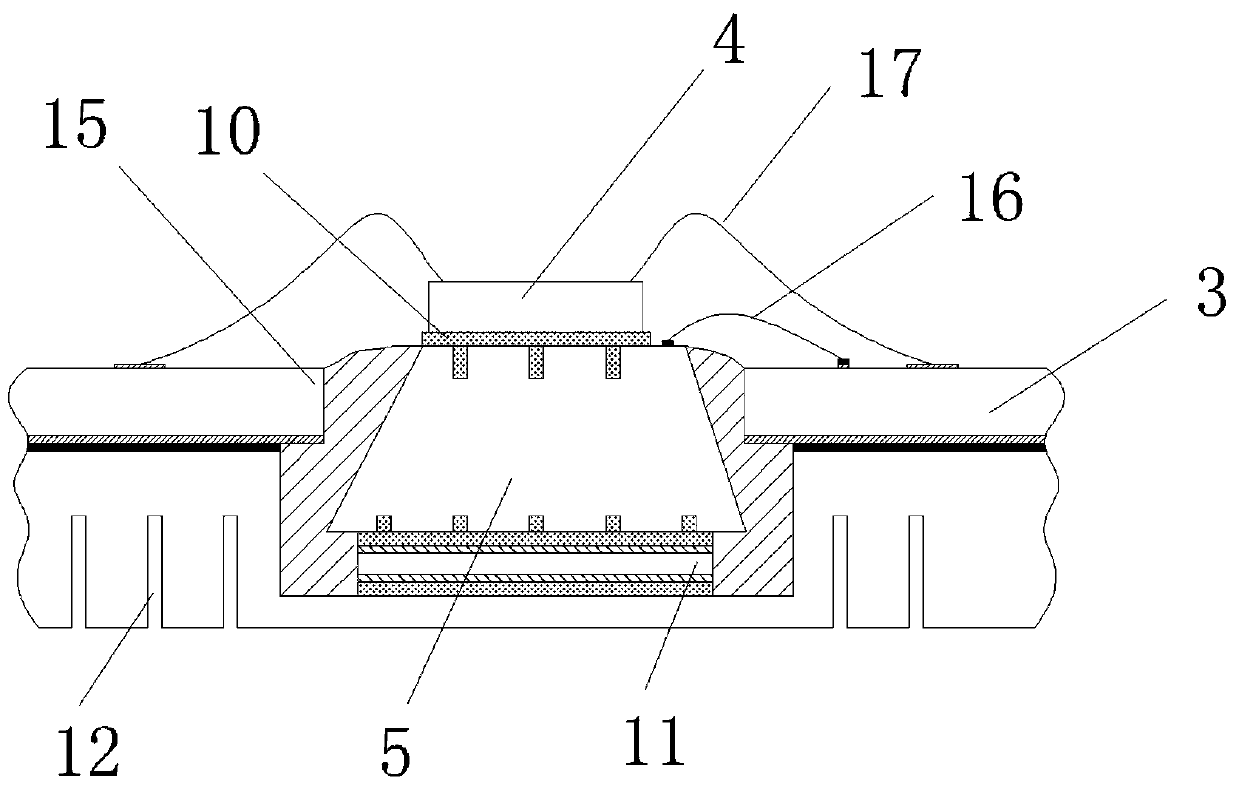
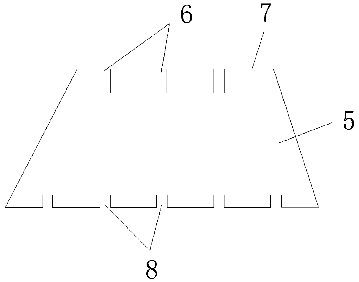
[0028] Such as figure 1 As shown, the present invention provides a thick-film power hybrid integrated circuit, including an upper cover 1, a housing base 2, a ceramic substrate 3 and a power chip 4 located in the housing base, and the bottom surface of the ceramic substrate 3 is welded to the inner bottom surface of the housing base 2; combine Figure 2~4 As shown, the shell base 2 is also provided with a copper heat sink block 5 in the shape of a trapezoidal table, the copper heat sink block 5 vertically penetrates the ceramic substrate 3 and is embedded in the inner bottom surface of the shell base 2; The surface is provided with an upper Tian-shaped groove 6, one side of the upper Tian-shaped groove 6 is the chip back electrode lead-out welding area 7, and the lower surface of the copper heat sink block 5 is provided with a lower Tian-shaped groove 8; Figure 4 It can be seen that the upper surface of the copper heat sink block 5 is divided into several upper division unit...


PUM

PropertyMeasurementUnit
angleaaaaaaaaaa

Abstract

The invention discloses a thick film power hybrid integrated circuit, which comprises an upper cover, a shell base, a ceramic substrate and a power chip, wherein the ceramic substrate and the power chip are located in the shell base, and the bottom surface of the ceramic substrate is welded to the inner bottom surface of the shell base; the shell base is further internally provided with a copper heat sink block in a trapezoidal table shape, and the copper heat sink block is vertically embedded in the ceramic substrate and the inner bottom surface of the shell base; the upper surface of the copper heat sink block is provided with an upper Chinese character 'tian'-shaped groove, one side of the upper Chinese character 'tian'-shaped groove is a chip back electrode leading-out end welding area, and the lower surface of the copper heat sink block is provided with a lower Chinese character 'tian'-shaped groove; the power chip is welded on the upper surface of the copper heat sink block; andan aluminum nitride transition sheet is welded between the lower surface of the copper heat sink block and the inner surface of the shell base. The copper heat sink block is arranged as a heat dissipation medium, so that the heat capacity and the heat dissipation performance of a high-power chip can be effectively improved; the copper heat sink block is arranged to be the shape of a trapezoidal table, so that the radial heat dissipation requirement of the power chip is met, and the heat dissipation capacity of the heat sink can be effectively improved.

Description

technical field [0001] The invention relates to the technical field of integrated circuits, in particular to a thick-film power hybrid integrated circuit. Background technique [0002] One of the main technical advantages of thick-film hybrid integrated circuits is the realization of power integration. The main reason is that the heat dissipation characteristics of the ceramic substrate and the metal shell base can be used to dissipate the heat generated by the power components in a timely manner. For power hybrid integrated circuits, the power chip is the main source of power, and its conventional assembly method is to directly solder the power chip on the ceramic substrate, or solder it to the ceramic substrate through a heat sink. [0003] For conventional low-power circuits, the base of the metal case is usually made of Kovar material; for medium and high-power circuits, the base of the metal case is usually made of 10# steel. Although the heat dissipation capacity of c...

Claims


Application Information

Patent Timeline
Patent Type & Authority Applications(China)
IPC IPC(8): H01L23/367H01L23/373
CPCH01L23/367H01L23/3675H01L23/3736
Inventor 夏俊生李寿胜肖雷李波尤广为侯育增李文才
Owner EAST CHINA INST OF OPTOELECTRONICS INTEGRATEDDEVICE
Learn More