A kind of anodized aluminum coating equipment

A coating equipment and anodized aluminum technology, which are applied to the device, coating, chemical instrument and method for coating liquid on the surface, etc., can solve the problems of uneven coating thickness of anodized aluminum, rising glue cost, and easy condensation of glue. , to achieve the effect of saving glue cost, reducing cleaning time and saving cleaning time

Active Publication Date: 2021-08-03
威海金光包装印刷材料有限公司
View PDF7 Cites 0 Cited by
  • Summary
  • Abstract
  • Description
  • Claims
  • Application Information

AI Technical Summary

Problems solved by technology

The domestic anodized aluminum foil generally has 4~5 layers. Most of the existing anodized aluminum coatings use a roll coater, that is, the glue is pressed on the anodized aluminum by the pressure between the rollers, but the existing anodized When coating aluminum coating equipment, on the one hand, the glue is in a fixed state, and the glue is in contact with the air, especially the glue on the edge is easy to condense, so on the one hand, the glue on the edge may deteriorate and fall off, thus mixing with the glue in the glue tank. This will affect the coating quality of the overall glue. On the other hand, after the glue is condensed, more glue will be attached, which will lead to an increase in the cost of the glue, and the cleaning of the condensed glue is more difficult and laborious. Secondly, the glue in the glue tank is in the In the static state, after the glue is used for a long time on the rubber roller, it will inevitably lead to insufficient uniformity of the glue, resulting in uneven coating thickness of the anodized aluminum, which affects the processing of the anodized aluminum. Therefore, there is an urgent need for the production of an anodized aluminum coating equipment

Method used


Image

  • A kind of anodized aluminum coating equipment
  • A kind of anodized aluminum coating equipment
  • A kind of anodized aluminum coating equipment

Examples


Embodiment

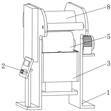
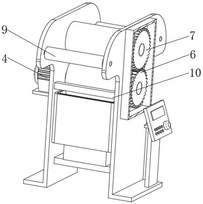
[0033] Such as figure 1 and figure 2 As shown, an anodized aluminum coating equipment includes: a coating shell 1, a control panel 2 is fixed on one side of the coating shell 1, a driving motor 4 is fixed on one side of the coating shell 1, and the output end of the driving motor 4 is connected to the rubber roller 5 is fixedly connected, the rubber roller 5 is rotationally connected with the coating shell 1, the driving gear 6 is fixed on one side of the rubber roller 5, and the driving gear 6 is provided with a driven gear 7 on one side, the driven gear 7 meshes with the driving gear 6, and the driven gear A pressure roller 8 is fixed at the axis of the gear 7, and the pressure roller 8 is rotatably connected with the coating shell 1, and auxiliary rollers 9 are arranged on both sides of the pressure roller 8, and the auxiliary roller 9 is rotatably connected with the coating shell 1, and one side of the rubber roller 5 is set There is a scraper 10, the scraper 10 is fixed...


PUM


Abstract

An electrochemical aluminum coating equipment, comprising: a coating shell, a rubber roller, a pressure roller, a driving motor, a gluing assembly, and a coating shell, the rubber roller is rotatably connected to the coating shell, and one side of the rubber roller The driving gear is fixed; the pressure roller is located above the rubber roller, and the pressure roller is rotatably connected with the coating shell, and a driven gear is provided on one side of the pressure roller, and the driven gear meshes with the driving gear The driving motor is arranged on one side of the coating shell, and the output end of the driving motor is fixedly connected to the rubber roller; the gluing assembly is located at the bottom of the rubber roller, and the gluing assembly is fixedly connected to the coating shell , the glue inside the glue tank is in a moving state through the coating component to ensure that the glue is uniform in all parts. On the other hand, the glue on the edge of the glue tank is continuously cleaned to the inside of the glue tank, saving glue costs and preventing the glue from deteriorating. Mixing with existing glue Thereby affecting the coating of the anodized aluminum plate, reducing the difficulty of cleaning the glue tank after use, and reducing the cleaning time.

Description

technical field [0001] The invention relates to the technical field of vacuum coating, in particular to an anodized aluminum coating equipment. Background technique [0002] Anodized aluminum foil is a hot stamping material made by coating and vacuum evaporation on a film base and adding a layer of metal foil. The thickness of anodized aluminum is generally (12, 16, 18, 20) um. 500~1500mm wide polyester film, generally 16um thick and 500mm wide film in China. [0003] Anodized aluminum foil is made by coating a release layer, an imaging layer, and embossing a laser pattern on a film sheet, after vacuum aluminum plating, then coating an adhesive layer, and finally rewinding the finished product. The domestic anodized aluminum foil generally has 4~5 layers. Most of the existing anodized aluminum coatings use a roll coater, that is, the glue is pressed on the anodized aluminum by the pressure between the rollers, but the existing anodized When coating aluminum coating equipme...

Claims


Application Information

Patent Timeline
Patent Type & Authority Patents(China)
IPC IPC(8): B05C1/08B05B15/50B01F15/00B01F7/18B01F7/16
CPCB05C1/0834B05B15/50B01F27/85B01F27/90B01F35/123B01F2101/36
Inventor 刘亚如
Owner 威海金光包装印刷材料有限公司
Why Eureka
Try Eureka