Ultrasonic spindle and ultrasonic machine tool comprising same

An ultrasonic and spindle technology, which is applied to the accessories of tool holders, fluids using vibration, metal processing machinery parts, etc., can solve the problems of difficult alignment, thin conductive rings and conductive inserts, and high alignment accuracy requirements. Achieve the effects of avoiding leakage, eliminating potential safety hazards, and simple and convenient operation

Pending Publication Date: 2020-01-14
CONPROFE MACHINE TOOLS CO LTD +1
View PDF0 Cites 2 Cited by
  • Summary
  • Abstract
  • Description
  • Claims
  • Application Information

AI Technical Summary

Problems solved by technology

[0004] 1. The power connector is located in the sleeve hole, which is difficult to disassemble and inconvenient for maintenance and replacement;
[0005] 2. The wire connected to the external power supply is fixed on the conductive ring of the power connector, so that when the power connector is disassembled, the wire can only be torn off, and repeated disassembly and assembly cannot be realized;
[0006] 3. The conductive ring and the conductive in

Method used


Image

  • Ultrasonic spindle and ultrasonic machine tool comprising same
  • Ultrasonic spindle and ultrasonic machine tool comprising same
  • Ultrasonic spindle and ultrasonic machine tool comprising same

Examples


Embodiment 1

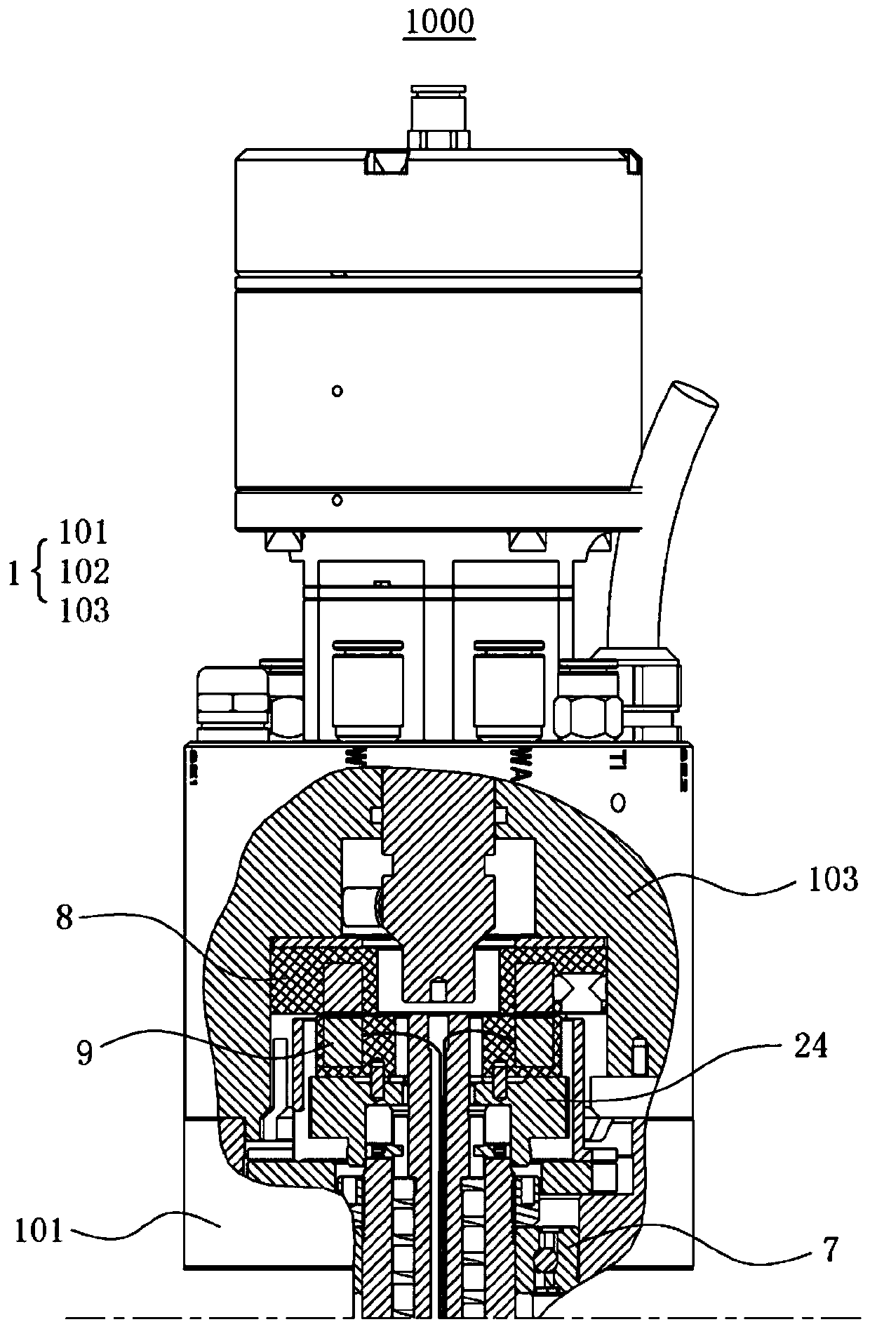
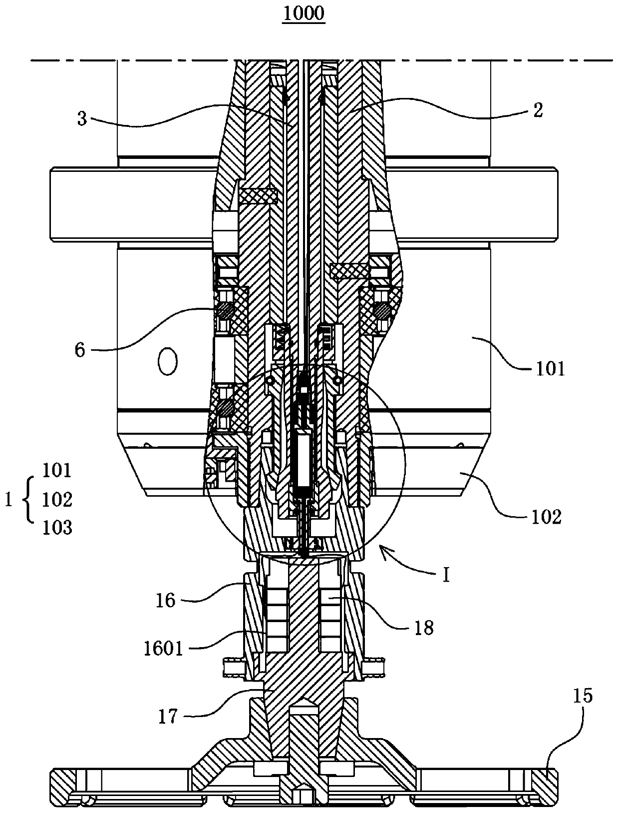
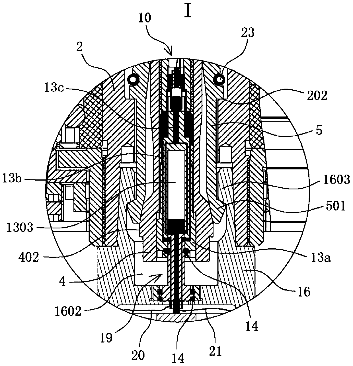
[0062] Such as Figure 1 to Figure 3 As shown, the embodiment of the present invention provides an ultrasonic spindle 1000, which mainly includes a cylinder base 1, a rotating shaft 2, a push rod 3, a sleeve body 4, a pull claw 5 and an ultrasonic processing assembly.

[0063] Such as Figure 1 to Figure 5 As shown, the cylinder base 1 is a fixed part, and the rotating shaft 2 is rotatably installed in the cylinder base 1; the inside of the rotating shaft 2 is provided with a cavity, and the push rod 3 is arranged in the cavity and can slide along the cavity, rotate The front end of the shaft 2 is provided with a sleeve hole 201 that communicates with the cavity; the sleeve body 4 is provided with a through hole 401 that runs through its front and rear ends, and the wall of the through hole 401 is provided with a first connecting thread 403, and the front end of the push rod 3 passes through The first connecting thread is screwed to the hole wall of the through hole 4, so tha...

Embodiment 2

[0089] Such as Figure 10 As shown, the embodiment of the present invention provides an ultrasonic machine tool, which mainly includes an ultrasonic power supply 2000 and the ultrasonic main shaft 1000 provided in Embodiment 1, wherein the wireless transmitting component 8 of the ultrasonic main shaft 1000 is electrically connected to the ultrasonic power supply 2000.

[0090]To sum up, the embodiment of the present invention provides an ultrasonic spindle 1000 and an ultrasonic machine tool including it. Compared with the prior art, the ultrasonic spindle 1000 has the advantages of easy maintenance, convenient disassembly and assembly, stable electrical conduction, high safety, The ultrasonic machine tool adopts the above-mentioned ultrasonic spindle 1000, so it also has the advantages of stable electrical conduction and good processing effect.


PUM


Abstract

The invention discloses an ultrasonic spindle and an ultrasonic machine tool comprising the same. For the ultrasonic spindle, the front end of a push rod is provided with an electric guide head, and adetachable sleeve body is internally provided with a conductive adapter, so that when the conductive adapter needs to be repaired or replaced, the sleeve body needs to be disassembled only to separately repair or replace the conductive adapter and then is installed on the push rod, and operation is simple and convenient; an electric wire is connected to the electric conduction head, and repeateddisassembly and assembly can be realized without being affected by the electric wire, so that the maintenance cost of the ultrasonic spindle can be effectively lowered; and meanwhile, for the ultrasonic spindle, by arranging an electrical connector at the rear end of a knife handle body and the conductive adapter in the sleeve body, the contact electrical connection part between an ultrasonic knife handle and a rotating shaft is located in the ultrasonic knife handle or the rotating shaft rather than being exposed at a gap between the ultrasonic knife handle and the rotating shaft, so that theelectric leakage phenomenon is capable of being avoided, and the potential safety hazard is eliminated.

Description

technical field [0001] The invention relates to the technical field of ultrasonic machining, in particular to an ultrasonic spindle and an ultrasonic machine tool including the same. Background technique [0002] Introducing a high-frequency vibration machining mechanism in the process of machining operations can not only improve the surface roughness of the cutting surface and improve machining accuracy, but also reduce cutting resistance and increase the life of the tool, so it is gradually widely used. [0003] The existing ultrasonic spindle is usually composed of a seat body, a rotating shaft and an ultrasonic tool handle. The rotating shaft is erected in the base body, and a sleeve hole is provided at the lower end, and a power connector is provided in the sleeve hole, and the conductive ring piece of the power connector is electrically connected with the external power supply through a wire; the ultrasonic handle is provided with a sleeve corresponding to the sleeve h...

Claims


Application Information

Patent Timeline
IPC IPC(8): B23B19/02B23B29/00B06B1/06B23Q1/70
CPCB06B1/06B23B29/00B23Q1/70
Inventor 颜炳姜蔡丹邝金田
Owner CONPROFE MACHINE TOOLS CO LTD
Why Eureka
Try Eureka