Shaft repair device under complex stress conditions

A technology with complex stress and conditions, applied in the direction of maintenance and safety accessories, metal processing machinery parts, other manufacturing equipment/tools, etc., can solve problems such as cumbersome operation, poor health of staff, poor repair accuracy, etc., and achieve reasonable structure Simplicity, prevention of environmental pollution, and low production cost

Pending Publication Date: 2020-01-14
河北瑞兆激光再制造技术股份有限公司
View PDF0 Cites 1 Cited by
  • Summary
  • Abstract
  • Description
  • Claims
  • Application Information

AI Technical Summary

Problems solved by technology

[0003] The purpose of the present invention is to provide a shaft repair device under complex stress conditions in order to solve the above problems, which solves the problem that the currently used laser cladding equipment and grinding equipment only have a single function, and n

Method used


Image

  • Shaft repair device under complex stress conditions
  • Shaft repair device under complex stress conditions
  • Shaft repair device under complex stress conditions

Examples


Embodiment Construction

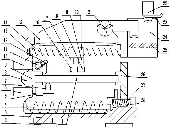
[0020] Such as figure 1 As shown, this specific embodiment adopts the following technical solutions: a shaft repair device under complex stress conditions, including a shaft 1, a base 2, a device casing 3, a screw transmission rod 4, an air pump 5, a first telescopic air rod 6, Air nozzle 7, first motor 8, fixture 9, second telescopic air rod 10, universal joint 11, lever gauge 12, second motor 13, screw mandrel 14, air suction hood 15, laser emitter 16, first cylinder 17. Dust suction grinding wheel 18, second cylinder 19, slider 20, first suction fan 21, water injection cylinder 22, valve 23, filter box 24, filter screen 25, support tailstock 26, regulating valve 27 and third motor 28 ; The bottom of the device shell 3 is fixedly connected with several bases 2; the top of the device shell 3 is provided with a suction cover 15; Net 25; the upper end of the filter box 24 is provided with a water injection cylinder 22, and a valve 23 is slidably connected to the water injectio...


PUM


Abstract

The invention discloses a shaft repair device under complex stress conditions. The shaft repair device under complex stress conditions includes a shaft, and further comprises a base, a device housing,a screw transmission rod, an air pump, a first telescopic gas rod, an air jet nozzle, a first motor and the like. The shaft repair device under complex stress conditions has reasonable and simple structure, low production cost and convenient installation. The shaft is placed in a clamp, a supporting tailstock holds up the shaft. The other end is locked through a regulating valve. A lever table does calibration. A second motor drives a sliding block on a screw rod to the specified position. A first air cylinder drives a laser transmitter to move down for cladding processing. A second air cylinder drives a dust collection grinding wheel to grind to the specified size. So the operation is convenient and efficient. Smoke and gas generated during laser cladding are inhaled into a filter box bya first suction fan in a suspended hood provided, adsorbed by an internal filter net and diluted with water injected from a top injector. The shaft repair device prevents environmental pollution by gas emission, while solves the problem that a large amount of harmful smoke and gas produced by laser cladding have bad effect on the health of workers.

Description

technical field [0001] The invention relates to the technical field of motor repair, in particular to a shaft repair device under complex stress conditions. Background technique [0002] The main shaft refers to the shaft that receives power from the engine or motor and transmits it to other parts. The main shaft is also called "optical axis" and is the abbreviation of "main optical axis". The main axis is a straight line passing through the center of the mirror surface and perpendicular to the mirror surface. The main axis of the lens or optical axis optical train is the connection line between the centers of each lens surface. During the long-term use of the axis, the axis will inevitably be worn, deformed, damaged and lose its normal state. If you do not analyze the working state of the shaft and predict its life, and do planned maintenance and overhaul, once an emergency occurs, it will cause serious losses to the company's entire line of production. Regular maintenance ...

Claims


Application Information

Patent Timeline
IPC IPC(8): B23P23/00B23Q11/00B23B31/30
CPCB23B31/302B23P23/00B23Q11/0046
Inventor 韩宏升郭树阁张月彬吴楠胡伟思金玉韩佳杰韩晓星贵永亮高飞韩金松
Owner 河北瑞兆激光再制造技术股份有限公司
Why Eureka
Try Eureka