Spindle oil cooling system, spindle oil temperature control method and machine tool cooling machine system

A cooling system and spindle oil technology, which is applied in the manufacture of tools, maintenance and safety accessories, metal processing machinery parts, etc., can solve the problems of uncontrollable spindle oil heat exchange, high equipment costs and operating costs, and improve energy utilization. , Improve the utilization rate and avoid the effect of excessive heat exchange

Active Publication Date: 2020-01-14
GREE ELECTRIC APPLIANCES INC
View PDF8 Cites 1 Cited by
  • Summary
  • Abstract
  • Description
  • Claims
  • Application Information

AI Technical Summary

Problems solved by technology

However, this solution only uses natural air to cool the oil temperature, which cannot control the heat exchange with the spindle oil, and requires additional fans to enhance convective heat exchange, resulting in high equipment and operating costs.

Method used


Image

  • Spindle oil cooling system, spindle oil temperature control method and machine tool cooling machine system
  • Spindle oil cooling system, spindle oil temperature control method and machine tool cooling machine system
  • Spindle oil cooling system, spindle oil temperature control method and machine tool cooling machine system

Examples


Embodiment 1

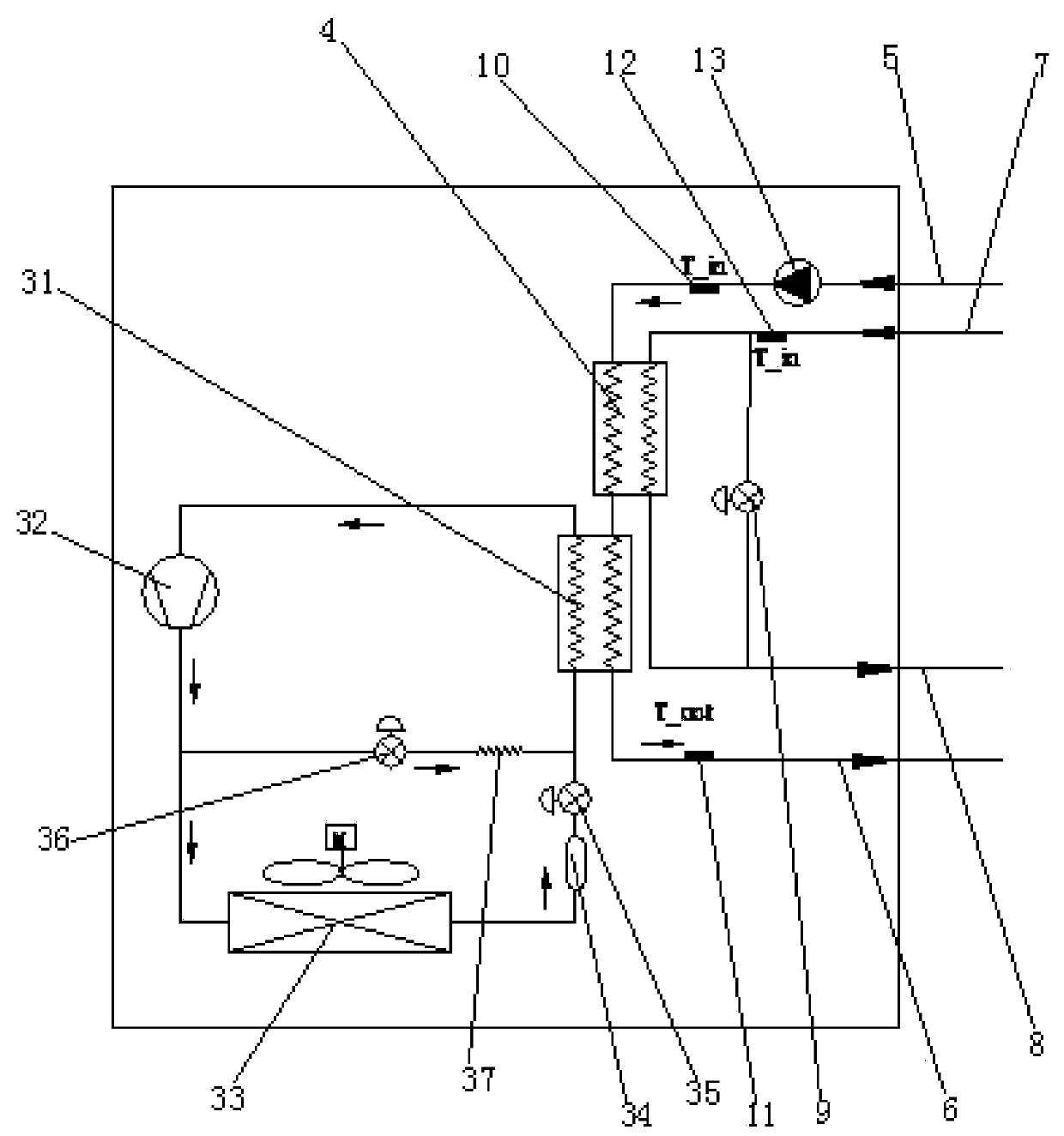
[0036] like Figure 1 to Figure 3 , a spindle oil cooling system, comprising a spindle oil cooling device 3, an oil inlet pipeline 5, an oil outlet pipeline 6, an oil inlet sensing probe 10, and an oil outlet sensing probe 11; the spindle oil cooling device 3 includes an evaporator 31; The oil outlet end of the evaporator 31 communicates with the oil outlet pipeline 6; it also includes an economizer 4, an inlet pipeline 7, an outlet pipeline 8, a bypass regulating valve 9 and an inlet sensor probe 12. Wherein, the economizer 4 is in heat exchange communication with the evaporator 31 and its oil inlet end is in communication with the oil inlet pipeline 5; the liquid inlet pipeline 7 is in communication with the liquid inlet end of the economizer 4 and is used for communicating Cutting fluid; the liquid outlet pipeline 8 communicates with the liquid outlet end of the economizer 4 and is used for passing the cutting fluid; the bypass regulating valve 9 is arranged between the liq...

Embodiment 2

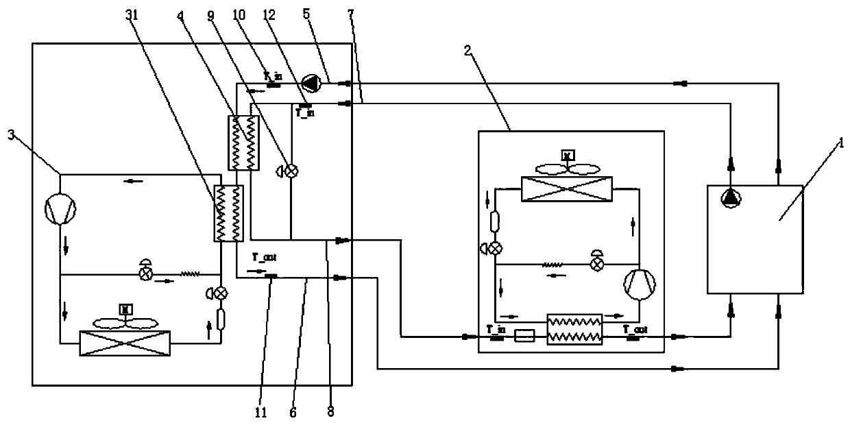
[0093] In this specific embodiment, the spindle oil cooling system of this example is basically the same as that of the embodiment, the difference is that the economizer 4 and the bypass regulating valve 9 of the spindle oil cooling system are changed to the cutting fluid cooling device 2, which can also achieve Energy saving purpose. However, because the cutting fluid cooling device 2 is inconvenient to obtain the set oil temperature of the spindle oil cooling system, it is impossible to precisely control the spindle oil temperature by controlling the heat exchange of the economizer 4 .


PUM


Abstract

The invention discloses a spindle oil cooling system. The system comprises a spindle oil cooling device, an oil inlet pipeline, an oil outlet pipeline, an oil inlet induction probe and an oil outlet induction probe. The spindle oil cooling device comprises an evaporator. The oil outlet end of the evaporator communicates with the oil outlet pipeline, and the spindle cooling device further comprisesan economizer, a liquid inlet pipeline, a liquid outlet pipeline, a bypass adjusting valve and a liquid inlet induction probe. The economizer is in heat exchange communication with the evaporator, the oil inlet end of the economizer communicates with the oil inlet pipeline, the liquid inlet pipeline communicates with the liquid inlet end of the economizer, the liquid outlet pipeline communicateswith the liquid outlet end of the economizer, the bypass adjusting valve is arranged between the liquid inlet pipeline and the liquid outlet pipeline, and the liquid inlet induction probe is arrangedon the liquid inlet pipeline. According to the spindle oil cooling system, waste heat of spindle oil can be recycled, and used for heating cutting liquid, electric heating of a cutting liquid coolingmachine is reduced, the aim of energy saving is achieved, meanwhile, temperature control precision of spindle oil can be ensured, the energy use rate is improved, and the invention further provides aspindle oil temperature control method and a machine tool cooling machine system with the spindle oil cooling system.

Description

technical field [0001] The present invention relates to the technical field of machine tool cooling, in particular to a spindle oil cooling system, a machine tool cooler system with the spindle oil cooling system, and a spindle oil temperature control method realized by the spindle oil cooling system . Background technique [0002] Existing CNC machining centers are generally equipped with spindle oil coolers and cutting fluid coolers. But these two cooling units work independently. When the machine tool is powered on, all supporting coolers are in running state. For example, when the oil temperature and cutting fluid temperature meet the set requirements, the oil pump and cutting fluid pump are also in working state. In most cases, the heat generated by the spindle is large, the spindle oil temperature is higher than the set temperature, and the spindle oil cooler is in a cooling state; the heat generated by the cutting side is small, and the cutting fluid is equipped wit...

Claims


Application Information

Patent Timeline
Patent Type & Authority Applications(China)
IPC IPC(8): B23Q11/12
CPCB23Q11/127B23Q11/141
Inventor 毕增利陈桂福赵成寅杨爱玲
Owner GREE ELECTRIC APPLIANCES INC
Why Eureka
Try Eureka