Cloth cutting device for clothing manufacture

A cutting device and fabric technology, applied in the field of fabric cutting, can solve the problem of high cost, achieve the effect of solving passivation problem, promoting grinding work, and improving cutting quality

Active Publication Date: 2020-01-14
湖南浚林服饰有限公司
View PDF9 Cites 10 Cited by
  • Summary
  • Abstract
  • Description
  • Claims
  • Application Information

AI Technical Summary

Problems solved by technology

[0004] The textile cloth cutting device in the above-mentioned patent has the following disadvantages: the desktop cutting device used in the above-mentioned copywriting is not suitable for large-scale cloth cutting, and at the same time, the cost is relatively high compared with small textile factories

Method used


Image

  • Cloth cutting device for clothing manufacture
  • Cloth cutting device for clothing manufacture
  • Cloth cutting device for clothing manufacture

Examples


Embodiment 1

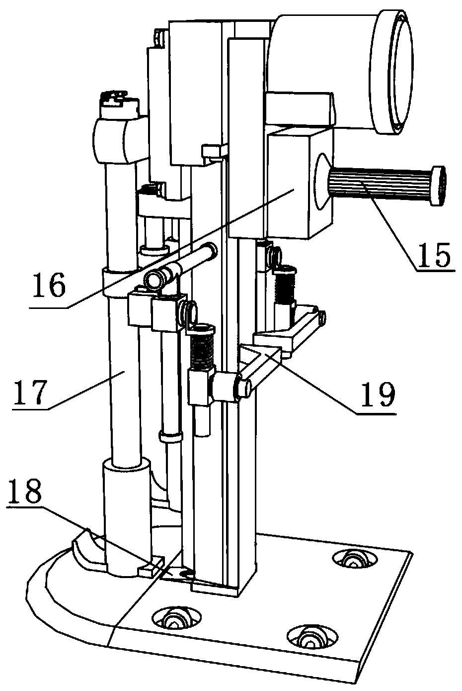
[0034] A cloth cutting device for clothing, such as figure 1 with image 3As shown, it includes a frame 1 and a cutting low plate 2, the bottom outer wall of the frame 1 is fixed with a knife rest 5 by bolts, and the bottom outer wall of the knife rest 5 is welded on the top outer wall of the cutting low plate 2; the cutting low plate 2 top outer wall is opened There are four installation holes 3, and the inner walls of each installation hole 3 are provided with rollers 4. The inner walls on both sides of the frame 1 are provided with chute 25, and the inner walls on both sides of the two chute 25 are slidably connected with the same first One slider, the outer walls of the opposite sides of the two first sliders are welded with mounting shafts 24, and the peripheral outer walls of the mounting shafts 24 are sleeved with fixing seats 27; The outer wall at the back of the first slider is welded with a U-shaped connecting frame 26, and the outer wall at the back of the U-shaped...

Embodiment 2

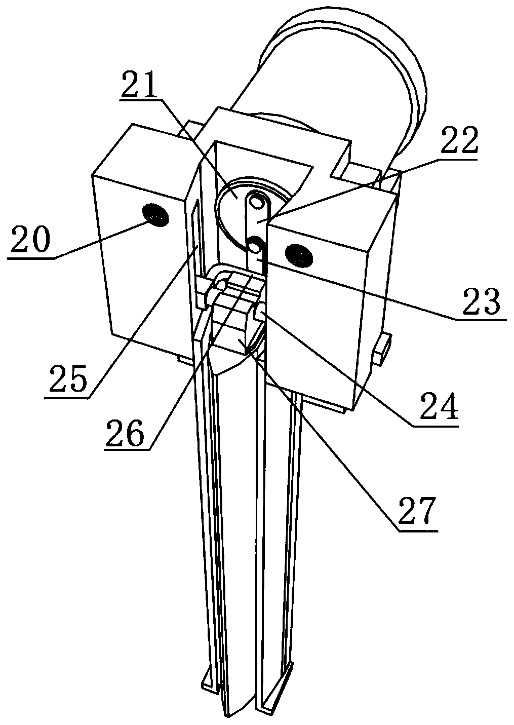
[0040] A cloth cutting device for clothing, such as figure 2 with Figure 5 As shown, in order to solve the passivation problem that occurs after the cutting knife 8 is used for a long time; this embodiment makes the following improvements on the basis of embodiment 1: the outer walls of the opposite sides of the two supports 19 are provided with a cutting unit, and the cutting The unit includes a telescopic spring 35, an L-shaped connector 36, a three-way pipe 37, a frosted block 38, a first slide bar 39, a connecting block 40, a second slide bar 41, a constant speed motor 42, a sleeve 43 and a third slide bar 44, one side of the outer wall of the constant speed motor 42 is fixed on one end of the bracket 19 by bolts, and the output end of the constant speed motor 42 is fixed with a sleeve 43 through the rotating rod, and the inner wall of the circumference of the sleeve 43 is plugged with a third slider. Rod 44, and the outer wall of the top circumference of the third slid...


PUM


Abstract

The invention discloses a cloth cutting device for clothing manufacture and relates to the technical field of cloth cutting, aiming to solve the problem that conventional bench type cutting devices are not adaptable to mass cutting of cloth. The cloth cutting device comprises a rack and a lower cutting plate; a blade carrier is arranged on the outer wall of the bottom of the rack, and the outer wall of the bottom of the blade carrier is welded to the outer wall of the top of the lower cutting plate; four mount holes are formed on the outer wall of the top of the lower cutting plate, and four rollers are respectively arranged inside the four mount holes; slide slots are respectively formed on the inner walls of two sides of the rack, two first sliders are slidably connected to the inner walls of two sides of the two slide slots respectively, the two first sliders are the same, mounting shafts are welded to outer walls of opposite sides of the two first sliders respectively, and holderssleeve the outer peripheral walls of the mounting shafts respectively; a cutting blade is fastened to the outer wall of the bottom of the holder, a U-shaped connecting frame is welded to the outer walls of backs of the two first sliders, and a second connecting plate is rotationally connected to the outer wall of the back of the U-shaped connecting frame. In application of the cloth cutting device, squeezing and fixing to single-layer or multi-layer cloth are facilitated, and accordingly, the cutting quality of the cutting blade is improved.

Description

technical field [0001] The invention relates to the technical field of cloth cutting, in particular to a cloth cutting device for clothing making. Background technique [0002] With the continuous development of the textile industry, cloth and cloth are not uncommon in our lives. However, in the process of textile production, cutting is an indispensable processing procedure. After the cloth is formed, it often needs to be processed according to customer requirements to crop it. Today's textiles are not only traditional hand spinning and weaving, but also non-woven technology, modern three-dimensional weaving technology, modern electrostatic nano-netting technology and other clothing, industrial and decorative textiles. Modern textile refers to A multi-scale structure processing technology for fibers or fiber aggregates. [0003] After searching, the Chinese patent application number is CN201810878922.0, which discloses a textile cloth cutting device, including a base, the ...

Claims


Application Information

Patent Timeline
Patent Type & Authority Applications(China)
IPC IPC(8): D06H7/00B24B3/36B24B41/02B24B47/12
CPCB24B3/361B24B3/368B24B41/02B24B47/12D06H7/00
Inventor 刘桂保刘功林谭件文
Owner 湖南浚林服饰有限公司
Why Eureka
Try Eureka