
Hydraulic motor gear pump with impeller arranged on inlet for pressurizing liquid supply

A technology of hydraulic motor and gear pump, which is applied in the direction of liquid displacement machinery, rotary piston type/swing piston type pump components, rotary piston type/swing piston type pump combination, etc., and can solve the problem of low efficiency of hydraulic motor pumps , Low efficiency of hydraulic pump, unfriendly man-machine and other problems, to achieve the effect of improving the problem of insufficient oil absorption, improving efficiency, and obvious oil absorption efficiency

Active Publication Date: 2020-01-14
LANZHOU UNIVERSITY OF TECHNOLOGY
View PDF8 Cites 3 Cited by
  • Summary
  • Abstract
  • Description
  • Claims
  • Application Information

AI Technical Summary

Problems solved by technology

[0002] The traditional hydraulic oil pump unit has large volume, high noise, external leakage, unfriendly man-machine, etc. Based on this, the design concept of the hydraulic motor pump came into being. The core idea is to integrate the driving motor and the hydraulic pump, eliminating the need Shaft unit, oil-cooled instead of fan-cooled motor, has the advantages of compact structure, low noise, good heat dissipation, man-machine friendliness, etc. There are mature series of motor pump products abroad, but the hydraulic pump is inherently insufficient in oil absorption, and it is quite serious and high-speed , the efficiency of the hydraulic pump is particularly low, so the efficiency of the hydraulic motor pump is not high, even lower than that of the traditional hydraulic oil pump set

Method used


Image

  • Hydraulic motor gear pump with impeller arranged on inlet for pressurizing liquid supply
  • Hydraulic motor gear pump with impeller arranged on inlet for pressurizing liquid supply
  • Hydraulic motor gear pump with impeller arranged on inlet for pressurizing liquid supply

Examples


Embodiment Construction

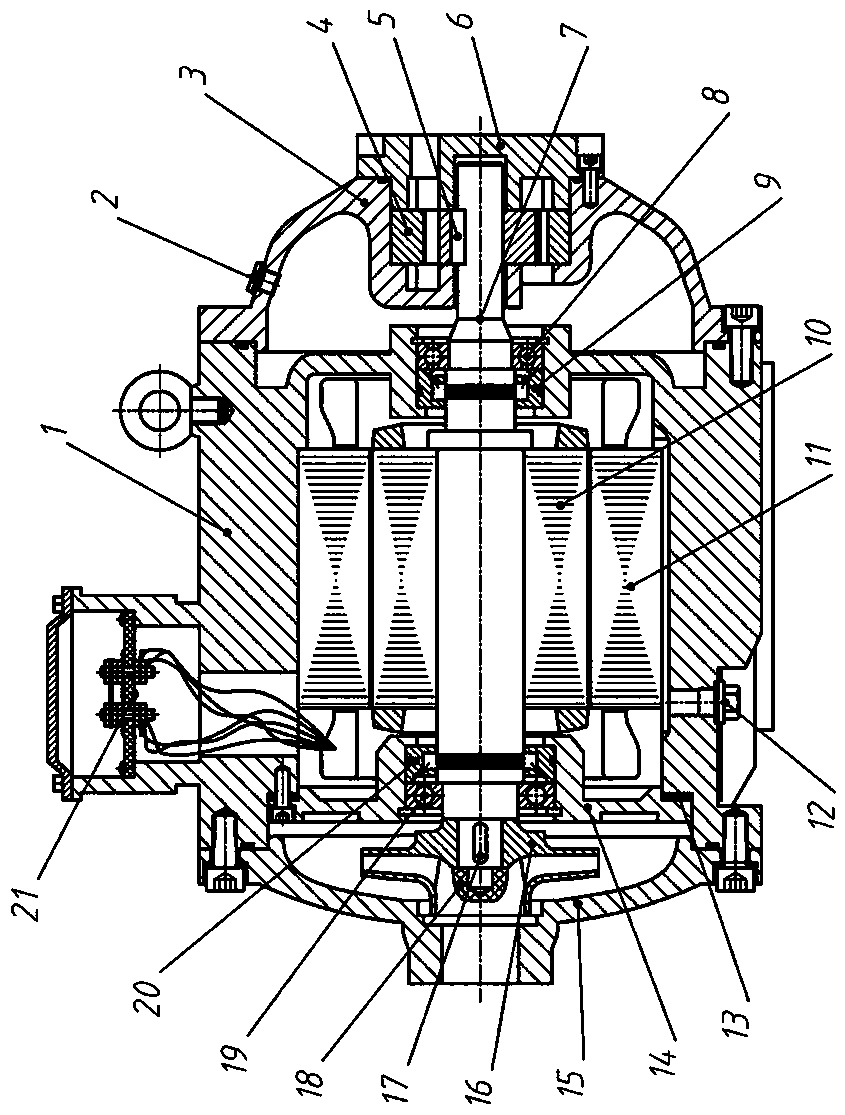
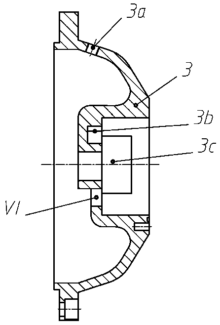
[0010] like Figure 1~Figure 5 As shown, the present invention is an imported hydraulic motor gear pump with impeller pressurization and liquid supply, including a housing 1, a vent hole screw plug 2, a front end cover 3, a gear pump group 4, a first flat key 5, and an oil outlet gland 6. Main shaft 7, first bearing 8, first seal 9, motor rotor 10, motor stator 11, oil drain plug 12, gasket 13, inner end cover 14, rear end cover 15, impeller 16, second Flat key 17, nut 18, second bearing 19, second seal 20, junction box assembly 21, the motor rotor 10 is installed on the main shaft 7 through interference fit, supported on the casing by the first bearing 8 and the second bearing 19 1, the gear set 4 is installed on the front end cover 3, connected with the main shaft 7 through the first flat key 5, and the impeller 16 is arranged between the rear end cover 15 and the inner end cover 14, and connected with the main shaft 7 with the second flat key 17 , both ends of the main sha...


PUM


Abstract

The invention discloses a hydraulic motor gear pump with impeller arranged on inlet for pressurizing liquid supply. The hydraulic motor gear pump is an integrated body of a motor, a centrifugal pump impeller and a gear pump; an oil inlet is provided with an impeller, and oil liquid reaches an oil suction port of the gear pump after being pressurized, so that the problem of insufficient oil absorption of the gear pump is well improved, especially at higher rotating speed, the oil absorption efficiency of the gear pump is improved more obviously, and meanwhile, cavitation noise generated due toinsufficient oil absorption is also avoided; and a motor rotor (10) is mounted on a main shaft (7) through an interference fit, a first bearing (8) and a second bearing (19) are supported on a housing(1), and a gear set (4) is mounted on a front end cover (3), is connected with the main shaft (7) through a first flat key (5), an impeller (16) is arranged between a rear end cover (15) and an innerend cover (14) and is connected with the main shaft (7) through a second flat key (17), and the two ends of the main shaft (7) are sealed through a first sealing member (9) and a second sealing member (20).

Description

technical field [0001] The invention relates to a hydraulic motor pump, in particular to an imported hydraulic motor gear pump with an impeller for pressurized liquid supply. Background technique [0002] The traditional hydraulic oil pump unit has large volume, high noise, external leakage, unfriendly man-machine, etc. Based on this, the design concept of the hydraulic motor pump came into being. The core idea is to integrate the driving motor and the hydraulic pump, eliminating the need Shaft unit, oil-cooled instead of fan-cooled motor, has the advantages of compact structure, low noise, good heat dissipation, man-machine friendliness, etc. There are mature series of motor pump products abroad, but the hydraulic pump is inherently insufficient in oil absorption, and it is quite serious and high-speed At this time, the efficiency of the hydraulic pump is particularly low, so the efficiency of the hydraulic motor pump is not high, even lower than that of the traditional hyd...

Claims


Application Information

Patent Timeline
Patent Type & Authority Applications(China)
IPC IPC(8): F04C11/00F04C15/00F04C15/06F04B23/12
CPCF04B23/12F04C11/00F04C15/00F04C15/0023F04C15/0096F04C15/062F04C2240/30
Inventor 冀宏孙飞徐瑞刘耀卓陈乾鹏刘新强魏列江
Owner LANZHOU UNIVERSITY OF TECHNOLOGY
Learn More