Thermal power plant waste gas purification equipment

A thermal power plant, exhaust gas purification technology, applied in the direction of gas treatment, chemical instruments and methods, combined devices, etc., can solve the problems of poor purification effect of exhaust gas purification devices, and achieve the effect of improving the effect

Inactive Publication Date: 2020-01-17
赣州市盈匠科技有限公司
View PDF0 Cites 0 Cited by
  • Summary
  • Abstract
  • Description
  • Claims
  • Application Information

AI Technical Summary

Problems solved by technology

[0004] The purpose of the present invention is to provide a thermal power plant exhaust gas purification equipment to solve the problem of poor purification effect of existing exhaust gas purification devices

Method used


Image

  • Thermal power plant waste gas purification equipment
  • Thermal power plant waste gas purification equipment
  • Thermal power plant waste gas purification equipment

Examples


Embodiment 1

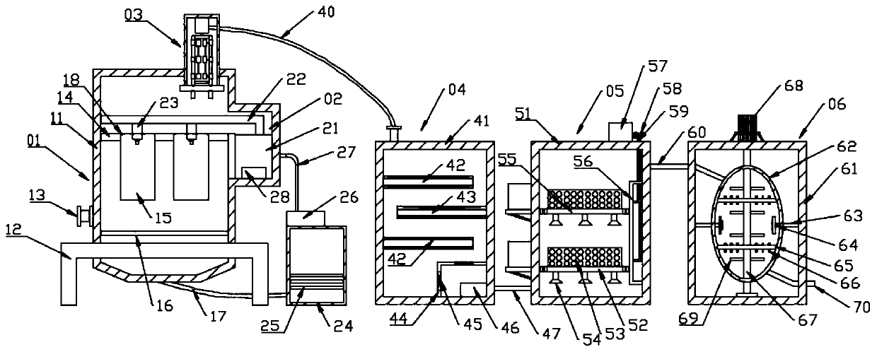
[0026] see Figure 1~3 , in an embodiment of the present invention, a thermal power plant exhaust gas purification equipment includes dust removal equipment 01 and purification equipment. The purification equipment includes a filter assembly 04, a reaction assembly 05, and a heating assembly 06. Coal mines are often used as fuel in thermal power generation. Contains a large amount of dust and harmful substances. Firstly, the dust is removed by the dust removal equipment 01, and then the exhaust gas is purified by the purification equipment, and then the dust and harmful substances in the exhaust gas are eliminated, so that the purified gas meets the emission requirements.

[0027] Further, the dust removal equipment 01 includes a dust removal box 11, the dust removal box 11 is placed on the base 12 for improving the stability of the dust removal box 11, a first air inlet 13 is provided on one side of the dust removal box 11, and the first air inlet The port 13 is used for the ...

Embodiment 2

[0034] A thermal power plant exhaust gas purification equipment, by setting dust removal equipment 01 and a purification device, it can not only remove a large amount of dust in the exhaust gas, but also process chemical substances, so that the discharged gas is cleaner; by setting dust removal equipment 01 The cleaning component 02 can not only clean the filter bag 15, but also wash the exhaust gas in the dust removal box 11. The used sewage is filtered through the first filter 25 and then enters the first water tank 21, so that it can be recycled, which is very simple Practical and save a lot of water resources.

[0035] The working principle of the present invention is: the gas enters the dust removal box 11 through the first air inlet 13, is filtered through the filter bag 15, is washed with water through the cleaning component 02, and then enters the adsorption component 03 through the through hole 18, and the cleaned Water recycling; after the gas enters the adsorption a...


PUM


Abstract

The invention discloses thermal power plant waste gas purification equipment, and relates to the field of waste gas purification. A purpose of the invention is mainly to solve the problem of poor purification effect of the existing waste gas purification device. The thermal power plant waste gas purification equipment comprises dust removal equipment and purification equipment, wherein the purification equipment comprises a filtering assembly, a reaction assembly and a heating assembly, the dust removal equipment comprises a dust removal box, a first gas inlet is formed in one side of the dustremoval box, a first fixing plate is fixed in the dust removal box, filtering bags are fixed at the bottom of the first fixing plate; through holes are formed in the connecting positions of the filtering bags and the first fixing plate, a plurality of the filtering bags are arranged, a cleaning assembly and an adsorption assembly are respectively arranged inside and at the top of the dust removalbox, the adsorption assembly is communicated to the filtering assembly through a first gas outlet, the filtering assembly is communicated to the reaction assembly through a second gas outlet, the reaction assembly is communicated to the heating assembly through a third gas outlet, and the heating assembly is communicated to the outside through a fourth gas outlet. According to the invention, theequipment has the improved waste gas purification effect.

Description

technical field [0001] The invention relates to the field of waste gas purification, in particular to waste gas purification equipment for thermal power plants. Background technique [0002] Thermal power generation generally refers to the general term for using the heat energy generated by the combustion of combustibles to heat water, turning the water into high-temperature, high-pressure water vapor, and then using the water vapor to drive a generator to generate electricity. Power plants that use combustibles as fuel are collectively referred to as thermal power plants; the main equipment systems of thermal power plants include: fuel supply system, water supply system, steam system, cooling system, electrical system and other auxiliary processing equipment. [0003] The thermal power generation process will produce a lot of pollution due to coal combustion, mainly including dust particles, ash, and flue gas discharged from the fuel combustion process; waste water and wast...

Claims


Application Information

Patent Timeline
IPC IPC(8): B01D50/00B01D53/04B01D53/75B01D53/26
CPCB01D53/0407B01D53/005B01D53/007B01D53/75B01D53/26B01D2257/91B01D2259/804B01D50/60
Inventor 曾万华
Owner 赣州市盈匠科技有限公司
Why Eureka
Try Eureka