
Equipment for degrading polytetrahydrofuran and recycling tetrahydrofuran and improved process

A technology of polytetrahydrofuran and tetrahydrofuran, which is applied in distillation separation, organic chemistry, chemical/physical/physical chemistry stationary reactors, etc., can solve the problems of economic loss, huge investment, blockage of heat exchanger tubes, etc., and achieve investment savings , the effect of less investment and high efficiency

Pending Publication Date: 2020-01-17
SINOPEC CHANGCHENG ENERGY CHEM NINGXIA CO LTD
View PDF0 Cites 1 Cited by
  • Summary
  • Abstract
  • Description
  • Claims
  • Application Information

AI Technical Summary

Problems solved by technology

The existing THF reactor does not set stirring, relying on the THF bottom pump for forced circulation stirring, due to the strong oxidizing properties of sulfuric acid and the high viscosity of polytetrahydrofuran, the local high temperature carbonization of PTMEG and the co-action of tar generation, the low circulation flow rate of the THF reactor bottom pump will cause The tubes of the heat exchanger are blocked, and the filter screen of the pump inlet is blocked, so that the reaction cannot proceed.
Since the THF reactor is used to dehydrate BDO to produce THF and degrade polytetrahydrofuran at the same time, once the above problems occur, the THF device will not be able to produce, which will cause greater economic losses.
However, if a separate process for degrading and refining THF is newly built, the investment will be huge

Method used


Image

  • Equipment for degrading polytetrahydrofuran and recycling tetrahydrofuran and improved process

Examples


Embodiment 1

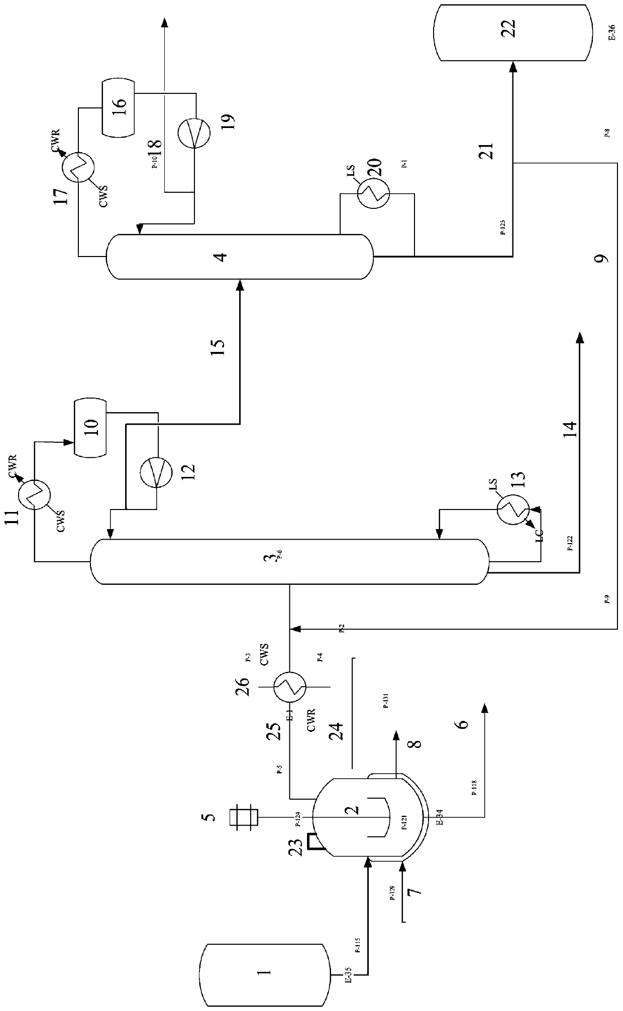
[0018] Put polytetrahydrofuran with a molecular weight of 300 g / mol into the degradation reactor 1 according to the ratio of 100:0.5 with the solid acid X, the feed rate is 1000Kg / h, and the mixture is heated to 170°C to generate THF, which is treated at normal pressure and in a pressurized tower , the purity of the obtained tetrahydrofuran is ≥99.7%, the water content is <300ppm, and the THF generation rate is 900Kg / h.

Embodiment 2

[0020] Put 1800g / mol molecular weight polytetrahydrofuran and solid acid 100:0.5 into the degradation reactor 1, the feed rate is 1000Kg / h, and the mixture is heated to 170°C to generate THF. The purity of tetrahydrofuran is ≥99.7%, the water content is <300ppm, and the hourly productivity is 900Kg / h.

Embodiment 3

[0022] Put polytetrahydrofuran with a molecular weight of 1800g / mol and solid acid 100:0.5 into the degradation reactor 1, heat the mixture to 190°C, generate THF and process it under normal pressure and in a pressurized tower. The purity of the obtained tetrahydrofuran is ≥99.7%. Water content < 300ppm, hourly productivity 940kg / h.


PUM


Abstract

The invention discloses equipment for degrading polytetrahydrofuran and recycling tetrahydrofuran and an improved process. According to the equipment, a material storage tank is connected with a degradation reactor through a pipeline, the degradation reactor is connected with an atmospheric column through a newly added gas phase extraction pipeline, the atmospheric column is connected with a pressurizing tower, and the pressurized tower is connected with a qualified tetrahydrofuran storage tank through a pipeline. The atmospheric column is connected with an atmospheric column condenser, an atmospheric column condensation tank and an atmospheric column top reflux pump through pipelines serially, and the pressurized tower is connected with a pressurized tower top condenser, a pressurized tower condensation tank and a pressurized tower top reflux pump through pipelines serially. As one degradation reactor, one tetrahydrofuran storage tank, the newly added gas phase extraction pipeline anda cooler are additionally arranged outside a conventional tetrahydrofuran production system, the atmospheric column and the pressurized tower of a conventional device are adopted for separation and refining of tetrahydrofuran, the newly added equipment and equipment of the conventional device are optimally combined, and thus a set of equipment for degrading polytetrahydrofuran and recycling tetrahydrofuran is formed. The equipment does not need to build a new rectification system, and is low in investment and high in benefit.

Description

technical field [0001] The invention belongs to the downstream fine chemical industry field of coal chemical industry, and specifically relates to equipment and an improved process for degrading polytetrahydrofuran and recovering tetrahydrofuran. Background technique [0002] The industrial production of polytetrahydrofuran (PTMEG) is mainly formed by cationic ring-opening polymerization of tetrahydrofuran (THF). When the polytetrahydrofuran plant was originally started up, due to many impurities in pipelines and equipment, operation and other reasons, about 1500t-3000t of unqualified PTMEG products would be produced. During normal production, the PTMEG device will produce 2~3% of PTMEG oligomers in the SPD (narrowing distillation) process, generally the average molecular weight is below 250-400, and the annual output of low-molecular polytetrahydrofuran is 2,000 tons based on 92,000 tons / year. tons or so. The sales price of these oligomers is low. Assuming that the market...

Claims


Application Information

Patent Timeline
IPC IPC(8): B01J19/18B01D3/00B01D3/14B01D3/32B01D3/42C07D307/08
CPCB01J19/18B01D3/009B01D3/146B01D3/42B01D3/32C07D307/08
Inventor 唐元周代红宋锋吴航宇张敏
Owner SINOPEC CHANGCHENG ENERGY CHEM NINGXIA CO LTD
Learn More