Elevator brake iron core automatic machining production line

An elevator brake, automatic processing technology, applied in the direction of lighting and heating equipment, conveyor control devices, chemical instruments and methods, etc., can solve the problems of increasing production costs, heavy physical strength, affecting production efficiency, etc., to avoid collision accidents, reduce Reduce production costs and improve the effect of precise positioning

Pending Publication Date: 2020-01-17
珠海汉迪自动化设备有限公司
0 Cites 3 Cited by

AI-Extracted Technical Summary

Problems solved by technology

At present, the iron core is mainly processed by the processing center equipment in the factory. During the processing, the loading and unloading of the iron core need to be manually operated, which will not only consume a lot of physical strength, but also affect the improvement of production efficiency.
Some factories will use manipulators to replace manual loading and unloading, but generally one manipulator corresponds to one or two machining center equipment. If the number of machining center equipment is l...

Method used

Positioning assembly 12 is also provided with detector 125 in place, detector 125 in place is connected with control unit, detector 125 in place is preferably a photoelectric sensor, detector 125 in place is positioned on top seat 1211 and emits the first towards parking stall 124 middle parts A photoelectric signal, when the material truck 11 enters the parking space 124 and the first guide assembly 122 is connected with the s...

Abstract

The invention provides an elevator brake iron core automatic machining production line. The production line comprises a material storage mechanism, a conveying mechanism, a robot loading unloading mechanism, an automatic cleaning and drying device and multiple machining center equipment; the material storage mechanism comprises a skip car and a positioning module; the skip car is positioned in thepositioning module; the robot loading and unloading mechanism is arranged on the conveying mechanism in a horizontal moving mode, and comprises a mechanical arm, a mounting base, a visual module, a height measuring module and two clamping modules; the mounting base is positioned on the mechanical arm; the two clamping modules are positioned on the mounting base; the visual module is positioned between the two clamping modules; the height measuring module is positioned on one side of one clamping module; the multiple machining center equipment is arranged in the length direction of the conveying mechanism; the automatic cleaning and drying device is arranged on one side of the conveying mechanism; and the control unit is connected with the robot loading unloading mechanism, the machining center equipment and the automatic cleaning and drying device. The production line can save the manpower, improve the efficiency and reduce the cost.

Application Domain

Drying gas arrangementsControl devices for conveyors +2

Technology Topic

EngineeringMaterial storage +4

Image

  • Elevator brake iron core automatic machining production line
  • Elevator brake iron core automatic machining production line
  • Elevator brake iron core automatic machining production line

Examples

  • Experimental program(1)

Example Embodiment

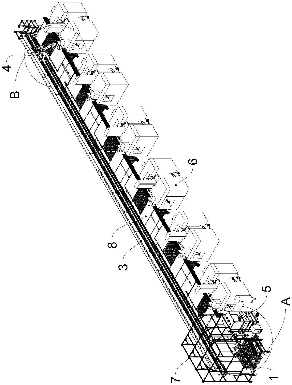
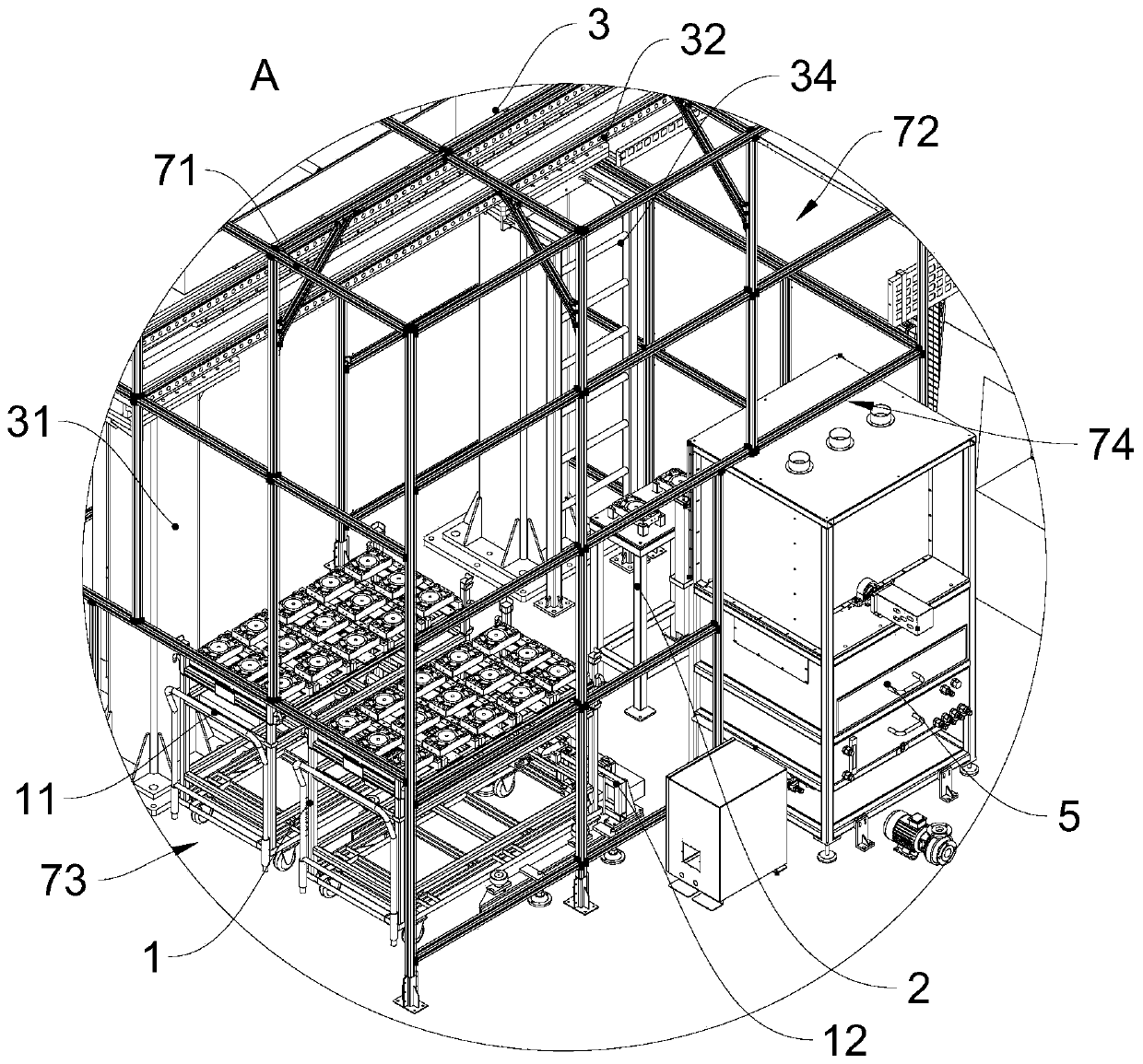
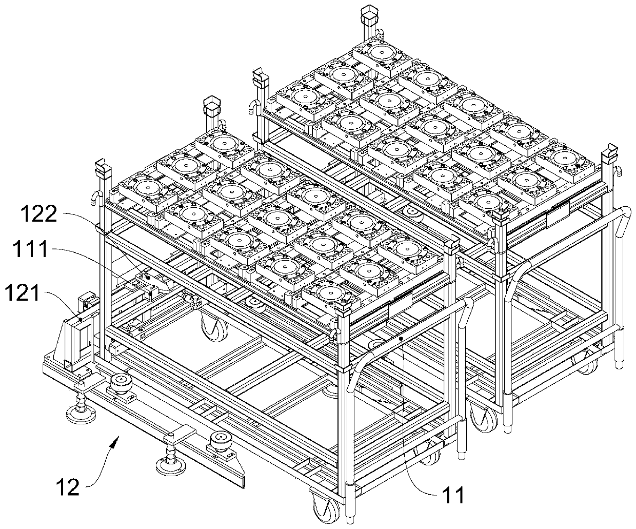
[0037] see figure 1 and figure 2 , figure 1 is a structural diagram of an embodiment of the present invention, figure 2 Yes figure 1 Enlarged image at A. The elevator brake iron core automatic processing production line includes a control unit, a material storage mechanism 1, a buffer table 2, a conveying mechanism 3, a robot loading and unloading mechanism 4, an automatic cleaning and drying device 5, and multiple processing center equipment 6. The control unit is respectively connected to the material The storage mechanism 1, the conveying mechanism 3, the robot loading and unloading mechanism 4, the automatic cleaning and drying device 5 are connected with the processing center equipment 6.
[0038]Conveying mechanism 3 comprises conveying frame 31 and two conveying guide rails 32, and two conveying guide rails 32 are positioned on conveying frame 31 horizontally and parallelly, and conveying guide rail 32 position is higher than the top of processing center equipment 6, and the two ends of conveying frame 31 are all arranged There are ladders 34 . The material storage mechanism 1, the buffer table 2 and the automatic cleaning and drying device 5 are all located at the first end of the conveying mechanism 3. The robot loading and unloading mechanism 4 is located on the conveying mechanism 3 and can move back and forth along the length direction of the conveying guide rail 32. Multiple processing The central equipment 6 is arranged on the same side of the conveying guide rail 32 along the conveying direction of the conveying mechanism 3. The material storage mechanism 1, the buffer table 2, the automatic cleaning and drying device 5 and each processing center equipment 6 are all located at the working position of the robot loading and unloading mechanism 4. within range. The buffer table 2 is provided with at least two positioning toolings 21 for temporarily storing processed workpieces and waiting for subsequent cleaning. The processed workpiece is put back on the material storage mechanism 1 after being cleaned and dried by the automatic cleaning and drying device 5 .
[0039] The first end of the conveying mechanism 3 is provided with a shading room 7, the shading room 7 includes a frame 71 and a plurality of shading plates, and a plurality of shading plates are laid on each side and the top surface of the frame 71, and the shading plates adopt a material that can block external light. material. The first end of the conveying guide rail 32, the material storage mechanism 1, and the buffer table 2 are all located in the shading room 7. The shading room 7 is provided with a first opening 72, a second opening 73, and a third opening 74. The first opening 72 and The second opening 73 is located on opposite sides of the light-shielding room 7 , and the third opening 74 is located on the side facing the conveying guide rail 32 . The robot loading and unloading mechanism 4 is inserted into the first opening 72 so as to move horizontally. The material storage mechanism 1 includes a feeding cart 11 and a positioning assembly 12. The positioning assembly 12 is fixed in the light-shielding room 7 and is located on the side of the second opening 73. The feeding cart 11 is inserted into the second opening 73 and connected with the positioning assembly 12. The automatic cleaning and drying device 5 is located in the third opening 74 and partially protrudes from the third opening 74 , extending to the outside of the shading room 7 .
[0040] see image 3 and Figure 4 , image 3 It is a structural diagram of an embodiment of the material storage mechanism of the present invention, Figure 4 It is a structural diagram of an embodiment of the positioning assembly of the present invention. The positioning assembly 12 includes a positioning frame 121 , a first guiding assembly 122 and two clamping assemblies 123 . The positioning frame 121 includes a top base 1211 and four support arms 1212, and the four support arms 1212 are horizontally arranged on the same side of the top base 1211 to form two "n"-shaped parking spaces 124, and the material truck 11 is located in the parking space 124 Inside. The support arm 1212 is provided with at least two follower wheels 1213 , and the follower wheels 1213 can be rollingly connected with the feeding cart 11 . The first guide assembly 122 is located on the side of the top base 1211 facing the support arm 1212 , the second guide assembly 111 is provided on the skip 11 , and the second guide assembly 111 is connected with the first guide assembly 122 . In one embodiment, the first guide assembly 122 includes a guide block, the second guide assembly 111 includes a guide slot, and the guide block engages with the guide slot. In another embodiment, the first guide assembly 122 includes a guide groove, the second guide assembly 111 includes a guide block, and the guide block engages with the guide groove.
[0041] The two clamping assemblies 123 are located on the top base 1211 and are arranged on both sides of the guide assembly. The clamping assembly 123 includes a clamping drive assembly 1231, a support block 1232, a first clamping block 1233 and a second clamping block 1234, The clamping drive assembly 1231 is located on the outer side of the top base 1211, the support block 1232 and the second clamping block 1234 are located on the inner side of the top base 1211, the middle part of the first clamping block 1233 is hinged with the support block 1232, the first clamping block The first end of the block 1233 is hinged to the clamping drive assembly 1231, the second end of the first clamping block 1233 is set opposite to the second clamping block 1234 and is separated from the preset space, and part of the frame of the material truck 11 is located in the preset space Inside. The second end of the first clamping block 1233 is provided with a first buffer block, the second clamping block 1234 is provided with a second buffer block, and the first buffer block and the second buffer block are oppositely arranged.
[0042] Positioning assembly 12 is also provided with in-position detector 125, and in-position detector 125 is connected with control unit, and in-position detector 125 is preferably a photoelectric sensor, and in-position detector 125 is positioned on the top seat 1211 and emits the first photoelectric signal toward the middle part of parking space 124 , when the material truck 11 enters the parking space 124 and the first guide assembly 122 is connected to the second guide assembly 111, the first photoelectric signal emitted by the in-position detector 125 is blocked by the material truck 11 and triggers the in-position detector 125 to send to the control unit In-position signal, at this time, the control unit controls the clamping drive assembly 1231 to drive the first clamping block 1233 to clamp the material trolley 11, so as to avoid the position deviation of the material trolley 11.
[0043] see Figure 5 , Figure 5 Yes figure 1 Enlarged view of middle B. The robot loading and unloading mechanism 4 includes a sliding seat 41 and a mechanical arm 42, and the mechanical arm 42 is a six-axis manipulator with six degrees of freedom. The first end of the mechanical arm 42 is connected with the sliding seat 41 . The sliding seat 41 is respectively connected with two conveying guide rails 32, and a rack 33 is arranged between the two conveying guide rails 32. The sliding seat 41 is provided with a sliding drive assembly 411 and a gear, and the gear and the rack 33 are meshed and connected to slide. The sliding drive assembly 411 is connected with the gear and is used to drive the gear to rotate. The sliding drive assembly 411 is preferably a motor, which can control the forward and reverse rotation of the gear.
[0044] A protective frame assembly 8 is provided between the conveying mechanism 3 and the processing center equipment 6 , the protective frame assembly 8 includes a protective top plate 81 , and the protective top plate 81 is arranged along the length direction of the conveying mechanism 3 . Both sides in the width direction of the protective top plate 81 are respectively connected to the top of the conveying frame 31 and the machining center equipment 6 . The protective top plate 81 is provided with a plurality of skylights 82 and a plurality of protective doors 83. The skylights 82 and the protective doors 83 are arranged in one-to-one correspondence. The skylights 82 are located at the loading and unloading side of the machining center equipment 6. equal in number. The protective door 83 is moved and blocked on the skylight 82 along the length direction of the protective top plate 81 . A protective driving assembly 84 is provided on one side of the protective door 83 . The protective driving assembly 84 is preferably a cylinder for driving the opening and closing of the protective door 83 . When the protective door 83 is opened, the second end of the mechanical arm 42 extends to the machining center equipment 6 through the skylight 82 .
[0045] see Image 6 and Figure 7 , Image 6 It is a structural diagram of the second end of the mechanical arm of the embodiment of the present invention, Figure 7 It is a structural diagram of an embodiment of the clamping assembly of the present invention. The second end of the mechanical arm 42 is provided with a mount 43 , a visual module assembly 44 , a height measuring assembly 45 and two clamping assemblies. Two clamping assemblies are arranged in parallel on the lower part of the mounting base 43, and are respectively used to clamp the workpiece to be processed and the processed workpiece. For the convenience of description, the clamping assembly that clamps the workpiece to be processed is referred to as the first clamping assembly 46 , the clamping assembly that clamps the processed workpiece is the second clamping assembly 47 . Set the connecting line direction of the first clamping component and the second clamping component as the X direction, set the direction perpendicular to the connecting line between the first clamping component and the second clamping component as the Y direction, and set the vertical direction Set to the Z direction.
[0046] The vision module assembly 44 is arranged on the mounting base 43 and located between the first clamping assembly 46 and the second clamping assembly 47 , and the height measurement assembly 45 is provided on the mounting base 43 and located at one side of the second clamping assembly 47 .
[0047] Vision module assembly 44 comprises camera 441, lens barrier 442 and barrier driving assembly 443, and the camera head of camera 441 is arranged downwards along Z direction, and lens barrier 442 blocks below the camera head of camera 441, and barrier driving component 443 and lens The baffle 442 is connected to drive the lens baffle 442 to move back and forth along the Y direction, and the baffle driving assembly 443 is preferably an air cylinder. Before the processing starts, the visual module assembly 44 takes a standard position image in advance. During the processing, the robot loading and unloading mechanism 4 takes a current position image and feeds it back to the control unit. The control unit compares the current position image with the standard position image, If the current position image is the same as the standard position image, it means that the robot loading and unloading mechanism 4 has reached the target position; if the current position image is different from the standard position image, the control unit adaptively adjusts the position of the robot loading and unloading mechanism 4 on the XY plane and angle.
[0048] The height measuring assembly 45 comprises a first height detection part 451, a second height detection part 452, a detection baffle 453 and two guide shafts 454, and the two guide shafts 454 are arranged on the mount 43 to move along the Z direction, and the first height The detection component 451 is located on the mounting seat 43 , the second height detection component 452 is located on the first end of the guide shaft 454 , and the first height detection component 451 is opposite to the second height detection component 452 . In this embodiment, the first height detection component 451 is a photoelectric switch, and the second height detection component 452 is a blocking member, which is used to block or reflect the second photoelectric signal emitted by the photoelectric switch.
[0049] The second end of the guide shaft 454 extends toward the clamping opening of the second clamping assembly 47 along the Z direction, and the detection baffle 453 is located on the second end of the guide shaft 454 and above the clamping opening. The middle part of the guide shaft 454 is provided with a stopper 455 and an elastic member 456, and the elastic member 456 is elastically abutted between the bottom of the mounting base 43 and the stopper 455, so that under normal conditions, the second height detection component 452 is in line with the first height. The detection parts 451 are on the same height. When the second clamping assembly 47 moves down to clamp the workpiece, the detection baffle plate 453 abuts against the upper surface of the workpiece, and when the detection baffle plate 453 is stopped by the workpiece and moves upward relative to the workpiece, the second height detection component 452 moves upward to match the workpiece. The first height detection part 451 is misplaced, and the first height detection part 451 is triggered to send a second photoelectric signal to the control unit. When the control unit receives the second photoelectric signal, the control unit controls the mechanical arm 42 to stop moving down, and at the same time controls the first clamping assembly 46 And/or the second clamping assembly 47 starts to clamp the workpiece.
[0050] The first clamping assembly 46 includes a locking assembly 461, a clamping drive assembly 462, a long side fixed block 463 and two jaws 464, the clamping drive assembly 462 is located on the lower side of the mounting base 43, and the two clamping jaws 464 are arranged in parallel At the lower part of the clamping driving assembly 462 , the clamping driving assembly 462 is preferably an air cylinder, which is used to drive the two clamping jaws 464 to be relatively close or relatively far away. The locking assembly 461 includes a locking driving assembly 4611, a floating joint 4612 and a limit block 4613. The locking driving assembly 4611 is preferably a cylinder, and the locking driving assembly 4611 is connected to the floating joint 4612 so that the floating joint 4612 can move back and forth along the Z direction , the limit block 4613 is located below the floating joint 4612, when the floating joint 4612 moves down along the Z direction, push the limit block 4613 to move down, so that the limit block 4613 is located on the outer side of one of the jaws 464, and the limit jaw 464 moves away from the other jaw 464, that is, restricts the two jaws 464 from releasing the workpiece. The long-side fixing block 463 is located on one of the jaws 464. Both ends of the long-side fixing block 463 are provided with clamping parts 4631, and the clamping parts 4631 extend toward the clamping mouth. The two clamping parts 4631 are arranged opposite to each other and separated preset distance. The clamping direction of the two clamping parts 4631 is perpendicular to the clamping direction of the two clamping jaws 464 . The structure of the second clamping component 47 is the same as that of the first clamping component 46 , which will not be repeated here.
[0051] see Image 6 , in order to facilitate preliminary cleaning of the finished workpiece, air blowing assemblies 48 are provided on both sides of the second clamping assembly 47 in the Y direction. The air blow assembly 48 includes an air blow installation plate 481 and a plurality of air blow joints 482, the air blow joint 482 communicates with the air supply unit, the first end of the air blow installation plate 481 is connected with the mounting base 43, the first end of the air blow installation plate 481 The two ends extend along the clamping opening, and a plurality of blowing joints 482 can be correspondingly arranged on the blowing mounting plate 481 according to the processing position on the workpiece.
[0052] see Figure 8 and Figure 9 , Figure 8 It is a structural diagram of the first perspective of the embodiment of the automatic cleaning and drying device of the present invention, Figure 9It is a structural diagram of the second perspective of the embodiment of the automatic cleaning and drying device of the present invention. The automatic cleaning and drying device 5 includes a main body frame 51 and an automatic door 52. The upper part of the first side of the main body frame 51 is provided with an inlet and outlet 511 and a door drive assembly 512, and the automatic door 52 is blocked on the inlet and outlet 511. Automatic door 52 is made as the bellows structure with telescopic function, and the bottom of automatic door 52 is fixed on the main body frame 51, and door drive assembly 512 is connected with the top of automatic door 52 and drives automatic door 52 telescopic movement up and down.
[0053] The main body frame 51 is provided with an overturn assembly 53 , a lifting translation assembly 54 , a filter assembly 55 and a water tank 56 sequentially from top to bottom, and the lifting translation assembly 54 is provided with a water spray assembly 57 and a first air injection assembly 58 . The top of the main body frame 51 is provided with three first smoke exhaust pipe joints 513, and the first smoke exhaust pipe joints 513 connect the inside of the main body frame 51 with the outside through the first smoke exhaust pipes. The filter assembly 55 is provided with three second smoke exhaust pipe joints 551, and the second smoke exhaust pipe joints 551 connect the inside of the filter assembly 55 with the outside through the second smoke exhaust pipes, so as to avoid accumulation of too much smoke in the internal space of the main body frame 51. Debris and dust will affect the cleaning effect.
[0054] The water tank 56 is detachably connected to the main frame 51 , and the water tank 56 is provided with a handle, and the handle is located on the second side of the main frame 51 . The water tank 56 is provided with a liquid level gauge 561 and two liquid level sensors 563, and the two liquid level sensors 563 are set up and down, and are respectively used for monitoring the highest warning water level and the lowest warning water level. The liquid level gauge 561 is used to display the current water level. The outside of the water tank 56 is provided with at least one drain 562. When the last liquid level sensor 563 detects that the water level inside the water tank 56 reaches the highest warning water level, the drain 562 can be opened for drainage; When the internal water level reaches the minimum warning water level, the drain port 562 is closed to stop draining.
[0055] The automatic cleaning and drying device 5 also includes a water pump 59, the water pump 59 is provided with a first water outlet, and the water outlet communicates with the water spray assembly 57 through a water pipe. In one embodiment, the water pump 59 is provided with a water inlet, and the water inlet communicates with the inside of the water tank 56. In another embodiment, the water pump 59 is provided with two water inlets, the first water inlet One end communicates with the inside of the water tank 56, and the second water inlet end communicates with the external water supply device.
[0056] see Figure 10 , Figure 10 It is a structural diagram of an embodiment of the turning assembly of the present invention. The turning assembly 53 includes a fixed seat 531, a turning tool 532 and a turning drive assembly 533. The middle part of the fixing seat 531 is provided with a turning opening 5311, and the turning tooling 532 is erected on the turning opening 5311. On one side of the turning port 5311, the turning driving assembly 533 is connected to the first end of the turning tool 532, so that the turning turning tool 532 can be driven to rotate around its own center in the horizontal direction. The fixed base 531 is provided with two rotating mounting bases 5312 mounting bases 43, and the two rotating mounting bases 5312 mounting bases 43 are respectively arranged at the two ends of the turning port 5311 and are respectively connected to the two ends of the turning tooling 532. The turning drive assembly 533 is preferably It is a motor, and the turning drive assembly 533 is connected to one end of the turning tool 532 .
[0057] The overturning assembly 53 also includes a splash guard 534 and a second air jet assembly 535 , the splash guard 534 is arranged along the edge of the overturning opening 5311 and extends upward. The second air injection assembly 535 is located on one side of the turning opening 5311 , a gap is provided on the splash guard 534 , and the second air injection assembly 535 is located in the gap. The second air injection assembly 535 includes a plurality of second air injection nozzles 5351 , and the second air injection nozzles 5351 can inject air toward the turning tool 532 .
[0058] see Figure 11 , Figure 11 It is a structural diagram of an embodiment of the turning tool of the present invention. The turning tool 532 includes a clamp mounting plate 5321 , two rotating shafts 5322 , multiple clamping seats and multiple clamp driving assemblies 5325 . The two rotating shafts 5322 are separately arranged at both ends of the fixture mounting plate 5321, and the two rotating shafts 5322 are coaxially arranged. The first rotating shaft 5322 is rotatably connected with a rotating mount 5312 mounting base 43 , and the second rotating shaft 5322 is rotationally connected with another rotating mounting base 5312 mounting base 43 and is connected with the turning drive assembly 533 at the same time. The middle part of the clamp mounting plate 5321 is provided with a relief opening, and the plurality of clamping seats are divided into two groups, and the two groups of clamping seats are respectively arranged on both ends of the avoidance opening, and the number of the clamping seats is equal to the number of the clamp driving assembly 5325, and the clamp driving assembly 5325 is set in one-to-one correspondence with the clamping seat.
[0059] The clamping seat includes a free block 5323 and a fixed block 5324, the fixed block 5324 is fixed on the fixture mounting plate 5321, the first end of the free block 5323 is hinged to the fixture drive assembly 5325, and the middle part of the automatic block is hinged on the fixture mounting plate through the connecting block 5321, the second end of the free block 5323 is located directly above the fixed block 5324 and forms a clamping opening for clamping the workpiece with the fixed block 5324.
[0060] At least one fixed block 5324 is provided with an in-position sensor 5326. The in-position sensor 5326 is preferably a proximity sensor for monitoring whether the workpiece is in position. When the workpiece is detected in position, it sends an in-position signal to the control unit, and the control unit controls The clamp drive assembly 1231 clamps the workpiece.
[0061] see Figure 12 , Figure 12 It is a structural diagram of an embodiment of the lifting and translation assembly of the present invention. The lifting and translation assembly 54 includes a lift frame 541, a lift drive assembly 542, a translation seat 543 and a translation drive assembly 544. The lower side of the fixed seat 531 is vertically provided with four first guide rods 545, and the lift frame 541 is sleeved on the vertically moving ground. On the first guide rod 545 , four first guide rods 545 are respectively arranged on the four corners of the lifting frame 541 . The quantity of the lifting drive assembly 542 is set as two, and the two lifting drive assemblies 542 are symmetrically arranged on the two ends of the length direction of the lifting frame 541 and are connected with the lifting frame 541, which can drive the lifting seat to move along the length direction of the first guide rod 545 . The lower side of the fixing seat 531 is provided with a plurality of limit rods 546. The limit rods 546 extend vertically downward and are used to abut against the lifting frame 541 to prevent the lifting frame 541 from rising too high and colliding with the workpiece.
[0062] The translation seat 543 is located on the lifting frame 541 to move horizontally. Two second guide rods 547 are horizontally arranged on the lifting frame 541 . The second guiding rods 547 are arranged along the length direction of the lifting frame 541 . The two ends of the translation base 543 in the length direction are provided with slider bases 5431, the slider bases 5431 are slidingly connected with the second guide rod 547, and the translation drive assembly 544 is arranged on one side of the second guide rod 547 along the length direction of the lifting frame 541. The translation driving assembly 544 is connected to one end of the translation base 543 and can drive the translation base 543 to move along the length direction of the second guide rod 547 . The lift drive assembly 542 and the translation drive assembly 544 are preferably air cylinders.
[0063] A cleaning assembly is provided on the translation base 543 . The cleaning assembly includes a water spray assembly 57 and a first air spray assembly 58 . The first air spray assembly 58 is arranged parallel to the water spray assembly 57 . The water spray assembly 57 includes a plurality of water spray heads 571 arranged side by side along the length direction of the translation base 543 , and each water spray head 571 is arranged vertically upward for spraying cleaning water vertically upward. The first jet assembly 58 includes a plurality of first jet nozzles 581, and a plurality of first jet nozzles 581 are arranged side by side along the length direction of the translation seat 543, and each first jet nozzle 581 is arranged vertically upwards for spraying vertically upwards. Gas, used to dry the workpiece surface after cleaning.
[0064] see Figure 13 , Figure 13 It is a structural diagram of an embodiment of the filter assembly of the present invention. The filter assembly 55 includes a filter box 552, a dust extraction box 553 and a filter screen 554. The filter box 552 is fixed on the main body frame 51, and the dust extraction box 553 is detachably connected in the filter box 552. The dust extraction box 553 can be used for shading Pull out the outside of room 7. The middle part of the dust removal box 553 is provided with a filter port, and the filter screen 554 is located on the filter port. The dust extraction box 553 is provided with a funnel portion 5531, and the funnel portion 5531 extends obliquely downwards along the inner edge of the dust extraction box 553 towards the filter port of the dust extraction box 553, so that the liquid and waste chips falling in the dust extraction box 553 can be Gather on the filter screen 554 for filtering. One side of the scrap box 553 is provided with a handle, and the handle of the scrap box 553 and the handle of the water tank 56 are on the same side of the main body frame 51 .

PUM

no PUM

Description & Claims & Application Information

We can also present the details of the Description, Claims and Application information to help users get a comprehensive understanding of the technical details of the patent, such as background art, summary of invention, brief description of drawings, description of embodiments, and other original content. On the other hand, users can also determine the specific scope of protection of the technology through the list of claims; as well as understand the changes in the life cycle of the technology with the presentation of the patent timeline. Login to view more.

Similar technology patents

Aluminum pipe bagging device

Owner:昆山市工业技术研究院有限责任公司

Method and device for testing webpage downloading speed of mobile terminal device

ActiveCN103581987Asave human effortIncrease sampling points
Owner:TENCENT TECH (SHENZHEN) CO LTD

Material pulverizing and sieving device

Owner:CHENZHOU JINTONG INFORMATION TECH CO LTD

Carrying trolley for large-size oil cylinder

Owner:ANQING TIANRUN ENG MACHINERY

Classification and recommendation of technical efficacy words

  • Increase productivity
  • save human effort

Preparation method of super-retarding type polycarboxylate superplasticizer

ActiveCN103848944AIncrease productivityUniform product
Owner:KZJ NEW MATERIALS GROUP CO LTD

Method for preparing epoxide

ActiveCN101348472Ashort crystallization timeIncrease productivity
Owner:CHINA PETROLEUM & CHEM CORP +1

Self-supporting car washing method and car washer

ActiveCN105957268Asave human effortsave water
Owner:盐城东方兴达农业发展有限公司

Drilled hole effective extraction radius measuring method based on gas content method

InactiveCN104121011AEliminate outstanding hazardssave human effort
Owner:CHINA COAL TECH ENG GRP CHONGQING RES INST

Vehicle-mounted visual sensing system with matched multi-cameras

InactiveCN106926800Asave human effortReduce time cost and economic cost
Owner:CHONGQING UNIV +1
Why Eureka
Try Eureka