High-energy tamping machine

A technology of tamping machine and liquid gunpowder, which is applied in the direction of sheet pile walls, blasting, construction, etc., can solve the problems of shallow tamping depth, low tamping frequency, large impact vibration, etc., and achieve full combustion, small pollution, and high force Delivers the effect of great depth

Inactive Publication Date: 2020-01-17
郑州鑫美高能打桩机有限责任公司
View PDF0 Cites 3 Cited by
  • Summary
  • Abstract
  • Description
  • Claims
  • Application Information

AI Technical Summary

Problems solved by technology

[0003] At present, there are many conventional machines for tamping the ground, but there are shortcomings such as shallow tamping depth and low work efficiency.
[0004] Although the dynamic tamping machine has a large tamping energy, the impact and vibration are also large. It is also very dangerous for a hammer of tens of tons to fall from tens of meters. The collision speed with the ground is high, causing splashes, surface hardening, and deep softness
Tamping is also less frequent

Method used


Image

  • High-energy tamping machine
  • High-energy tamping machine
  • High-energy tamping machine

Examples


Embodiment Construction

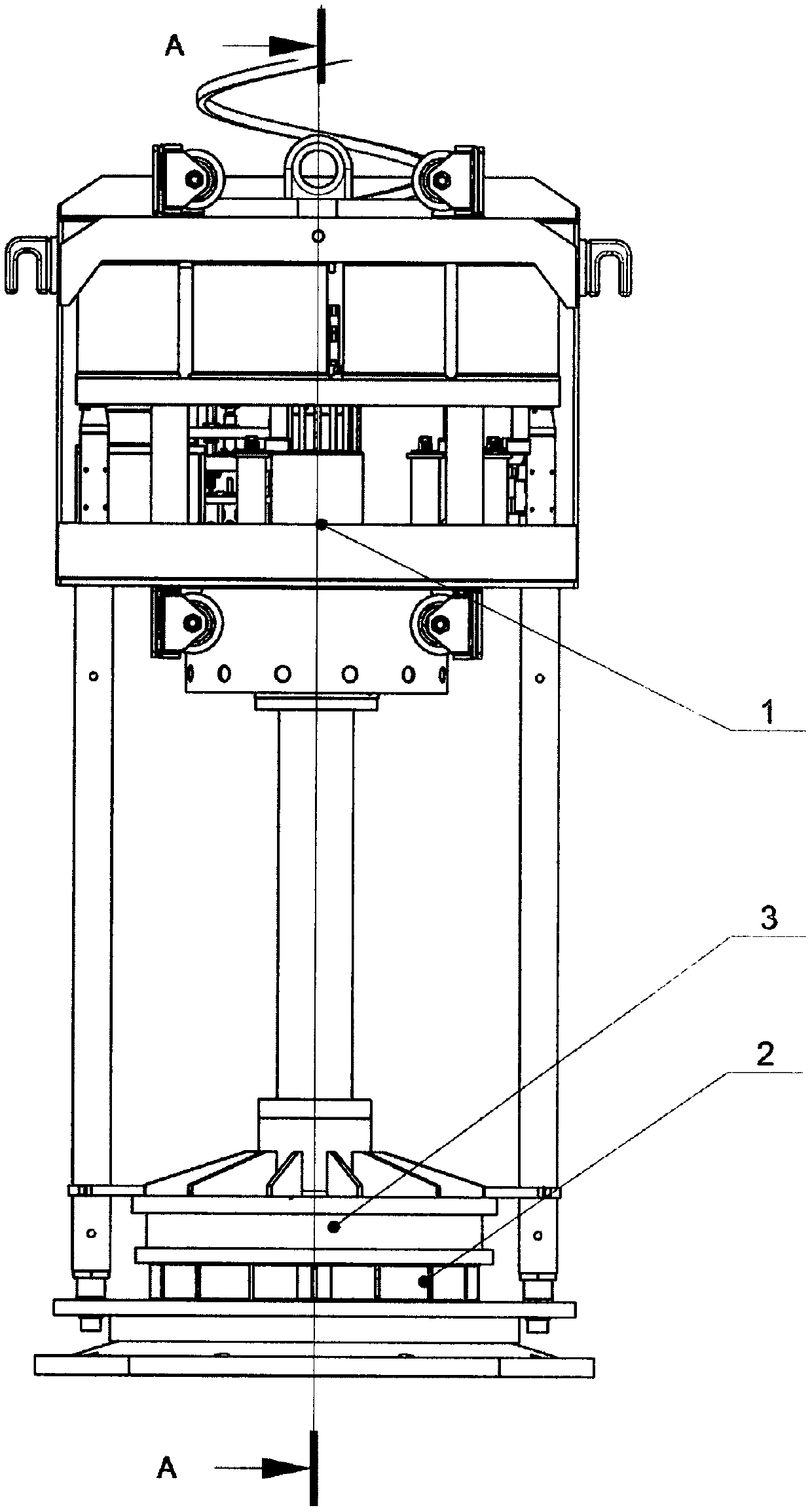
[0016] figure 1 It is a general diagram of a high-energy rammer. It consists of an impact part 1, a pressure part 2 and a buffer 3. The impact part 1 is a moving part up and down, which includes a container for holding liquid gunpowder, a pump for delivering liquid propellant, a one-way valve for injecting liquid gunpowder, a combustion chamber and a hollow tube equivalent to a gun barrel, and a muffler for reducing plosive sound. Hydraulic system and linkage devices, etc.; the pressure part 2 is in contact with the ground, and the force transmitted from above acts on the ground to make the ground compact; the buffer 3 is located in the buffer between the impact part 1 and the pressure part 2 Components, in the static state, the weight of the impact part is borne by the buffer, and the weight of the impact part is transferred to the pressure part, and the pressure part transfers the overall weight to the ground.

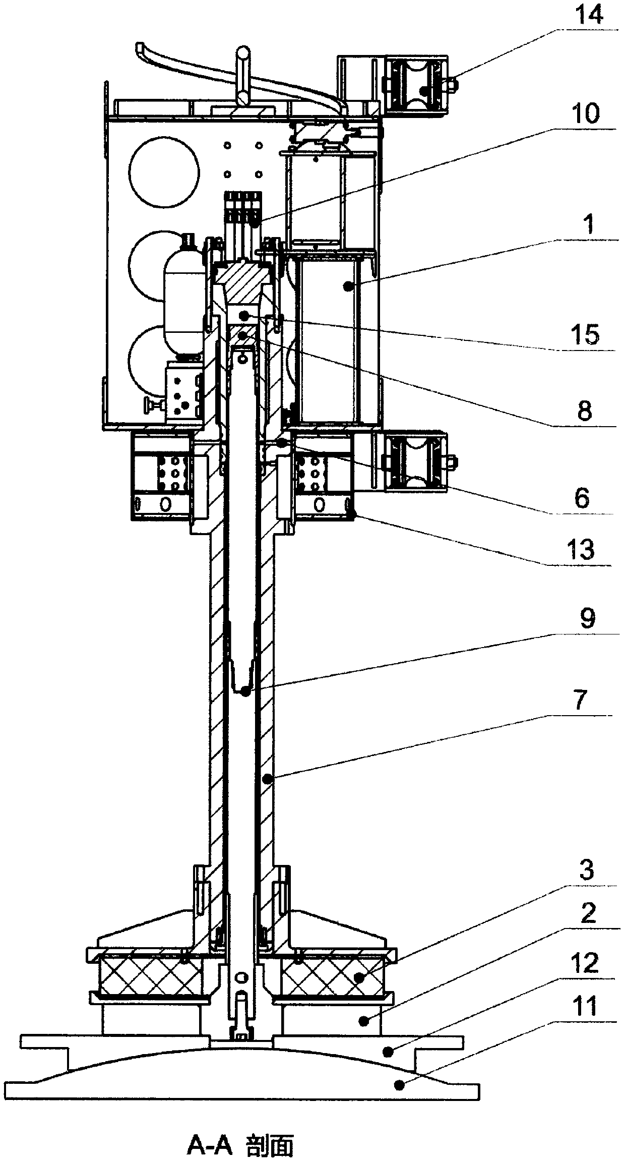
[0017] figure 2 yes figure 1 The A-A section in the figure...


PUM


Abstract

The invention discloses a high-energy tamping machine. According to the high-energy tamping machine, a liquid explosive is adopted as tamping energy, the upper portion serves as an impacting part, thelower part serves as a pressing part, and a buffer is arranged between the impacting part and the pressing part. A combustion chamber with a downward opening is arranged on the impacting part, the upper end of the combustion chamber is closed, a closed combustion space is formed from the upper end face of a piston to the closed upper end of the combustion chamber, the liquid explosive is injectedinto the combustion chamber through a check valve and is ignited through electric ignition or chemical ignition, and high-pressure fuel gas is generated; on one hand, the piston, a piston rod and thepressing part are pushed downwards, and the ground below the high-energy tamping machine is compacted; on the other hand, the impacting part is pushed to move upwards; and the impacting part falls under the action of the gravity or a reset spring, the buffer is compressed, buffering force and tamping force are generated, and secondary tamping is formed.

Description

technical field [0001] The invention belongs to a tamping machine in engineering machinery, which uses liquid gunpowder, also known as liquid propellant, as the energy source for tamping, and can effectively tamp the ground and increase the bearing capacity of the ground. Background technique [0002] Liquid gunpowder (liquid propellant) was mostly used in military fields such as launching artillery shells, launching missiles, and launching rockets in the past. It has the performance of combustion and explosion and has a lot of energy. Based on the structure of the liquid propellant artillery, we have modified it and invented a high-energy tamping machine, which uses the force generated by the explosion of liquid gunpowder to compact the ground and uses the rebound energy to tamp the ground. [0003] Conventional machines for compacting the ground are many at present, but there are deficiencies such as shallow depth of compaction and low work efficiency. [0004] Although t...

Claims


Application Information

Patent Timeline
Patent Type & Authority Applications(China)
IPC IPC(8): E02D7/12E02D7/06F42D3/00
CPCE02D7/06E02D7/12F42D3/00
Inventor 郭伟王会莉
Owner 郑州鑫美高能打桩机有限责任公司
Why Eureka
Try Eureka