Chemical raw material drying device

A technology for drying equipment and chemical raw materials, which is applied in drying, drying machines, drying of granular materials, etc. It can solve the problems of poor air permeability and unevenness of material particles, and large space for drying drums, so as to increase air permeability and facilitate Even contact and drying effect

Inactive Publication Date: 2020-01-17
吴燕林
View PDF0 Cites 14 Cited by
  • Summary
  • Abstract
  • Description
  • Claims
  • Application Information

AI Technical Summary

Problems solved by technology

[0002] Coated potassium sulfate granules are a kind of slow-release potassium fertilizer. The existing production method is to process potassium sulfate powder through granulation, sieving, drying, cooling and coating. At present, in the production process of potassium sulfate granules, The drying drum is generally used for drying the particles. Due to the large space of the drying drum, the accumulation of material particles has poor air permeability, which makes the drying insufficient and uneven, which affects the quality of the product.

Method used


Image

  • Chemical raw material drying device
  • Chemical raw material drying device
  • Chemical raw material drying device

Examples


Embodiment 1

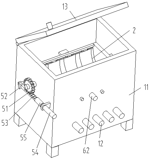
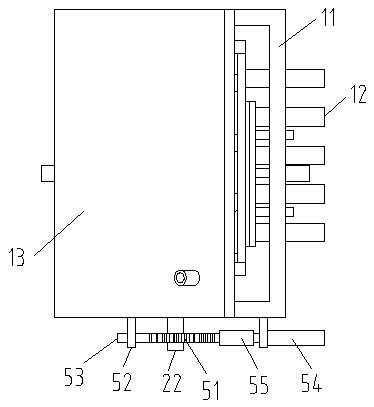
[0026] Such as Figure 1-7 and Figure 10 As shown, a chemical raw material drying device provided by the present invention includes a box body 11, and a group of air delivery pipes 12 are fixedly connected to the bottom of the box body 11. The air delivery pipes 12 are used to input dry hot air into the box body 11. On the box body 11 The side is hingedly connected to the sealing cover 13, which can be opened when needed. The upper side of the sealing cover 13 is provided with an exhaust pipe connected to the inner cavity of the box body 11. The inside of the box body 11 is rotatably connected to the distribution box 2. The distribution box 2 includes an upper frame 21 , the upper frame 21 is a square frame, and the opposite sides of the upper frame 21 are respectively fixedly connected to the rotating shaft 22, and the rotating shaft 22 is respectively connected to the inner wall of the corresponding box body 11 in rotation, and one of the rotating shafts 22 extends out of t...

Embodiment 2

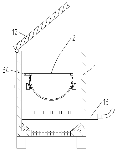
[0028] Such as Figure 3-6 As shown, on the basis of Embodiment 1, the inside of the box body 11 is rotated and connected to the sieve plate 31, the sieve plate 31 is uniformly provided with vent holes, the aperture of the vent hole is smaller than the particle diameter of the chemical raw material particles to be dried, and the inner wall of the box body 11 is fixedly connected. Support plate 32, support plate 32 is fixedly connected with support spring 33 at one end of the upper side of sieve plate 31, one side of material distribution box 2 is fixedly connected with horizontal plate 34, and the inner wall of box body 11 is fixedly connected with support plate 35, and support plate 35 is provided with a sliding hole , vertically slidingly connect the square vertical bar 36 in the sliding hole, the upper end of the square vertical bar 36 is fixedly connected to the baffle plate 37, and the first spring 38 is fixedly connected between the baffle plate 37 and the support plate 3...

Embodiment 3

[0031] Such as figure 1 , image 3 and Figure 7-10 As shown, on the basis of Embodiment 2, the bottom of the curved plate 24 is fixedly connected to the wave plate 61 at one end close to the hook spring 25, and the outer side of the box body 11 is fixedly connected to the first cylinder 62, and the telescopic rod of the first cylinder 62 extends into the box body 11 inside and fixedly connected to the stopper 63 at the end, the side of the stopper 63 close to the arc plate 24 is arranged in an arc shape, the side of the stopper 63 close to the arc plate 24 is fixedly connected to the rubber block 64, and the rubber block 64 is close to the arc One side of the shape plate 24 is arranged in a wave shape, and the rubber block 64 is arranged corresponding to the wave plate 61 and the wave surface of the two is suitable. There is a guide hole, and the guide rod 65 passes through the guide hole and is slidably connected. During the periodical swing of the material distribution box...


PUM


Abstract

The invention discloses a chemical raw material drying device. The chemical raw material drying device comprises a box body; the bottom of the box body is fixedly connected with a set of air conveyingpipes; the upper side of the box body is hinged with a sealing cover; a separation box is rotationally connected into the box body; the separation box comprises an upper frame; the upper frame is a square frame; rotating shafts are fixedly connected to two opposite sides of the upper frame; the rotating shafts are rotationally connected with the corresponding inner side walls of the box body; semicircular plates are fixedly connected to the two ends of the bottom of the upper frame; a set of arc plates hinged to the upper frame is alternately arranged between the two semicircular plates; oneends of the arc plates are hinged to one side of the bottom of the upper frame; and the other ends of the arc plates are fixedly connected with the other side of the bottom of the upper frame throughhanging hook springs. A gap is formed between the two connected arc plates, and is intermittently generated in continuous swinging process; and materials in the separation box fall from the generatedgap to fully contact with drying hot air on the lower side to achieve the drying uniformity.

Description

technical field [0001] The invention relates to the technical field of drying equipment, in particular to a chemical raw material drying device. Background technique [0002] Coated potassium sulfate granules are a kind of slow-release potassium fertilizer. The existing production method is to process potassium sulfate powder through granulation, sieving, drying, cooling and coating. At present, in the production process of potassium sulfate granules, Drying drums are generally used for drying particles. Due to the large space of the drying drums, the accumulation of material particles has poor air permeability, which makes the drying insufficient and uneven, which affects the quality of the product. Contents of the invention [0003] The object of the present invention is to propose a drying device for chemical raw materials in order to solve the shortcomings in the prior art. [0004] In order to achieve the above object, the present invention adopts the following techn...

Claims


Application Information

Patent Timeline
Patent Type & Authority Applications(China)
IPC IPC(8): F26B17/26F26B21/00F26B25/00F26B25/04F26B25/18
CPCF26B17/26F26B21/001F26B25/002F26B25/04F26B25/18F26B2200/08
Inventor 不公告发明人
Owner 吴燕林
Why Eureka
Try Eureka