Device for controlling hydrogen release efficiency of alloy hydrogen storage equipment

A release efficiency and hydrogen storage technology, applied in electrical components, fuel cell heat exchange, fuel cell additives, etc., can solve the problems of low hydrogen absorption and desorption rate, and achieve the effect of increasing the filling rate

Active Publication Date: 2020-01-17
安徽伯华氢能源科技有限公司
View PDF7 Cites 1 Cited by
  • Summary
  • Abstract
  • Description
  • Claims
  • Application Information

AI Technical Summary

Problems solved by technology

[0007] The technical problem to be solved by the present invention is: how to deal with the low hydrogen absorption and desorption rate of the alloy hydrogen storage equipment existing in the prior art

Method used


Image

  • Device for controlling hydrogen release efficiency of alloy hydrogen storage equipment
  • Device for controlling hydrogen release efficiency of alloy hydrogen storage equipment

Examples


Embodiment 1

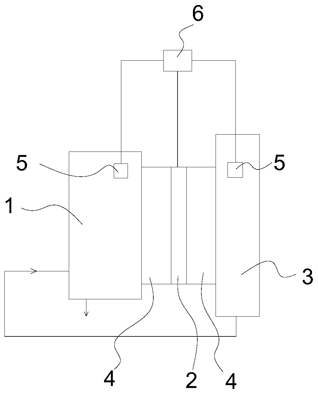
[0028] Such as figure 1 As shown, a device for controlling the hydrogen release efficiency of an alloy hydrogen storage device includes a fuel cell 1, a semiconductor refrigeration chip 2, an alloy hydrogen storage device 3, a heat transfer medium 4, two temperature sensors 5, and a controller 6; The hydrogen device 3 is connected to the fuel cell 1 through pipelines, and the alloy hydrogen storage device 3 provides hydrogen for the fuel cell. The bottom of the fuel cell 1 is provided with a water outlet. 1 is connected to the alloy hydrogen storage device 3, and the heat conduction medium 4 is mainly installed on the outer surface of the fuel cell 1 and the alloy hydrogen storage device 3, and the heat conduction medium 4 is in close contact with the semiconductor refrigeration sheet 4 and is coated with heat conduction silicone grease, wherein One temperature sensor 5 is set on the fuel cell 1 and connected to the controller 6 , and the other temperature sensor 5 is set on t...

Embodiment 2

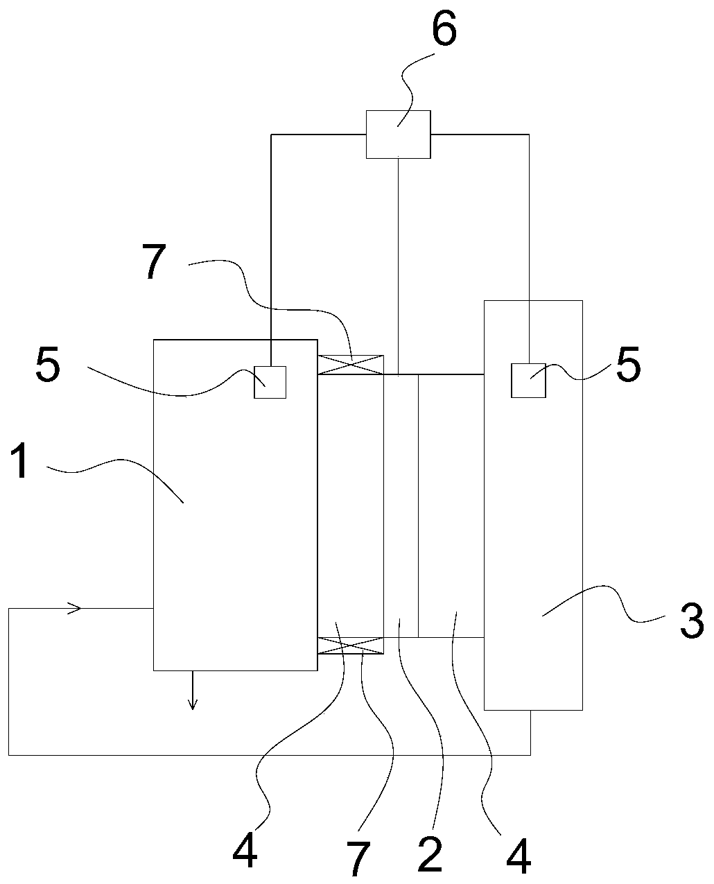
[0038] Such as figure 2 As shown, on the basis of the first embodiment, heat sinks 7 are added at the upper and lower ends of the heat transfer medium installed on the surface of the fuel cell 1 .

[0039] The cooling device 7 is an air cooling device or a water cooling device.

[0040] In this embodiment, the heat dissipation device 7 is a heat dissipation fan.

[0041] When the alloy hydrogen storage device 3 is filled with hydrogen, the semiconductor refrigerating sheet 2 changes the direction of the energized current to exchange the hot and cold ends, and the cold end cools down the alloy hydrogen storage device 1 that generates heat due to the filling of hydrogen through the heat conduction medium 4, so as to Increase the hydrogen filling rate, and turn on the cooling fan at the hot end to reduce its temperature.


PUM


Abstract

The invention discloses a device for controlling hydrogen release efficiency of alloy hydrogen storage equipment. The device comprises a fuel cell, a semiconductor chilling plate, the alloy hydrogen storage equipment and a heat-conducting medium, the alloy hydrogen storage device is connected with the fuel cell through a pipeline, and the cold end and the hot end of the semiconductor chilling plate are connected with the fuel cell and the alloy hydrogen storage device through heat conduction media respectively. The invention has the beneficial effects that when the fuel cell works, the hot endof the semiconductor chilling plate heats and preserves heat of the alloy hydrogen storage equipment through the heat-conducting medium, and the cold end dissipates heat and cools the fuel cell through the heat-conducting medium, so that the alloy hydrogen storage equipment and the fuel cell are kept in a proper temperature interval to achieve the optimal working efficiency; when the alloy hydrogen storage device is filled with hydrogen, the semiconductor chilling plate exchanges the cold end and the hot end by changing the current direction, the cold end cools the alloy hydrogen storage device through the heat conduction medium to improve the hydrogen filling rate, and the hot end takes cooling measures to reduce the temperature of the alloy hydrogen storage device.

Description

technical field [0001] The invention relates to a hydrogen fuel cell system and the application field of alloy hydrogen storage technology, in particular to a device for controlling the hydrogen release efficiency of alloy hydrogen storage equipment. Background technique [0002] As the research and application of hydrogen fuel cells are paid more and more attention, the storage and transportation of hydrogen has also become the focus of attention. Among them, alloy hydrogen storage is an extremely convenient and ideal hydrogen storage method. The use of hydrogen storage alloys for hydrogen storage not only has the characteristics of large hydrogen storage capacity, low energy consumption, low working pressure, and convenient use, but also eliminates the need for Bulky steel container for easy and safe storage and transport. [0003] Since the hydrogen storage alloy has the characteristics of releasing a large amount of heat during the hydrogen absorption chemical reaction ...

Claims


Application Information

Patent Timeline
Patent Type & Authority Applications(China)
IPC IPC(8): H01M8/04007H01M8/04701
CPCH01M8/04037H01M8/04074H01M8/04708H01M8/04738Y02E60/50
Inventor 马凯成姜慧徐宝成王广飞崔雪刘青巨正文
Owner 安徽伯华氢能源科技有限公司
Why Eureka
Try Eureka