A Hybrid Plasmon Resonator with High Quality Factor

A technology of plasmonic resonator and high quality factor, which is applied in the field of resonators and transmission lines, can solve the problems that the plasmonic quality factor and resonance strength are difficult to have at the same time, and achieve considerable application prospects, high-sensitivity sensing, Effect of Enhancing Quality Factor and Resonance Strength

Active Publication Date: 2021-01-05
SOUTHEAST UNIV
View PDF11 Cites 0 Cited by
  • Summary
  • Abstract
  • Description
  • Claims
  • Application Information

AI Technical Summary

Problems solved by technology

But like other microwave resonators, artificial localized surface plasmons also have the problem that it is difficult to have both quality factor and resonance strength

Method used


Image

  • A Hybrid Plasmon Resonator with High Quality Factor
  • A Hybrid Plasmon Resonator with High Quality Factor
  • A Hybrid Plasmon Resonator with High Quality Factor

Examples


Embodiment 1

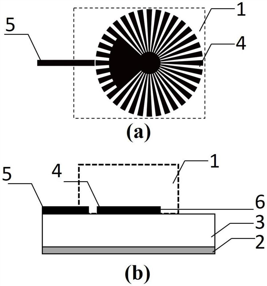
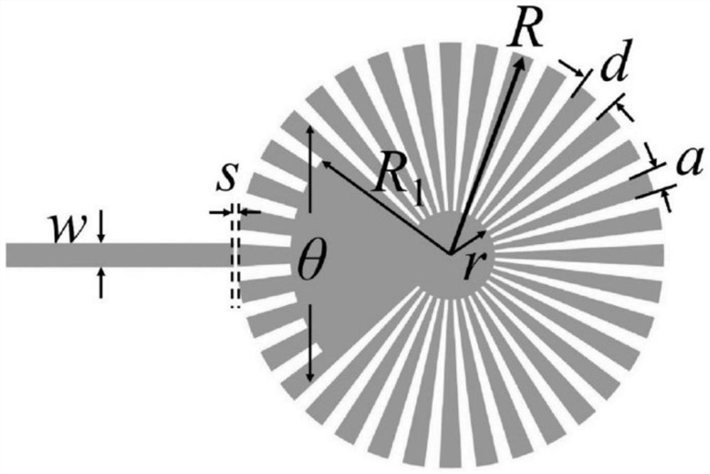
[0047] The structure of the hybrid plasmonic resonator in this embodiment is as follows Figure 1-3 shown. The geometric parameters are: R=12mm, r=2.5mm, d=2.09mm, a=0.6*d=1.26mm, R 1 =9mm, θ=86°. The structure is excited by a 50Ω microstrip line, the dielectric substrate 3 is a 0.5mm thick F4B plate, its dielectric constant is 2.65, the loss tangent is 0.001, the width of the microstrip line is w=1.34mm, and the gap between the microstrip line and the resonator is s = 0.2 mm.

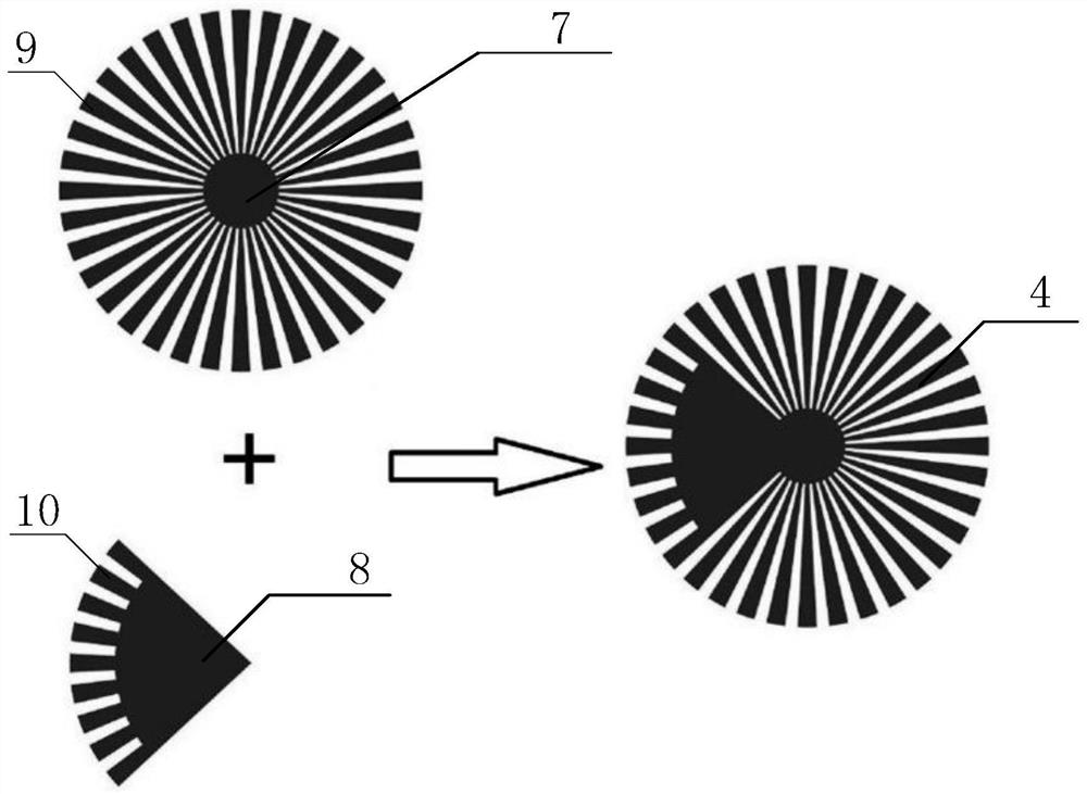
[0048] Simulation S of artificial localized surface plasmon resonator (SLSP), sector resonator (PR) and hybrid plasmon resonator (Hybrid) (resonator body) disclosed by the present invention 11 curve like Figure 4 shown. The resonant peak of the hybrid plasmonic resonator is at 9.16GHz, S 11 =0.04 (-22.8dB), quality factor Q=142. The artificial localized surface plasmon resonator (SLSP) is in the magnetic plasmon mode at 8.96GHz, and Q=44.8. Due to the superposition of two resonators, the artif...

Embodiment 2

[0055] Sensing area 1 is a closed area or an open space covered by an outer wall, and its material can be gas, liquid, solid or a mixture of the three; the refractive index of the sensing area material is in the range of (1,3).

[0056] This embodiment adopts the same geometric structure as that of Embodiment 1, for the application of the resonator in the sensing of different dielectric environments (refractive index range 1-1.8), and the electromagnetic simulation results are as follows Figure 7 . Figure 7 is the reflectivity of the resonator body (S 11 ) spectrum; where the black solid line is the reflectivity S when the refractive index of the sensing area is equal to 1 (air) 11 . When the refractive index of sensing region 1 gradually increases, we can see that S 11 Redshift of spectral resonant frequency, frequency sensitivity to refractive index change is 1.1GHz.RIU -1 . The artificial surface plasmon resonator has a sensitivity of 0.27GHz.RIU -1 . Therefore, th...

Embodiment 3

[0058] This embodiment adopts the same geometric structure as Embodiment 1, and it detects the thickness of the F4B dielectric plate, and its experimental test results are as follows Figure 8 , the hollow circle, solid circle, hollow triangle and solid triangle in the figure are S when the thickness of the F4B dielectric substrate is 0.5mm, 1mm, 1.5mm and 2mm respectively 11 Curve, the black solid line is the S of the resonator body when the dielectric substrate is not covered 11 spectrum. It can be seen that as the thickness of the surface dielectric material increases, its resonance peak presents an obvious red shift.


PUM

PropertyMeasurementUnit
thicknessaaaaaaaaaa
thicknessaaaaaaaaaa
thicknessaaaaaaaaaa

Abstract

The invention discloses a hybrid plasmon resonator with a high quality factor, and the resonator is of a layered structure, wherein the uppermost layer is a sensing region layer, the lowermost layer is a large-area metal ground, the upper layer of the large-area metal ground is a dielectric substrate, and the lower layer of the sensing region layer is a transmission layer where a resonator body and a microstrip line are located; the resonator body is formed by superposing an artificial local area surface plasmon resonance structure and a fan-shaped resonance structure; and a gap is formed between the microstrip line and the resonator body. The hybrid Plasmon resonator has the advantages of high quality factor and high resonance intensity through interference among a plurality of resonancemodes.

Description

technical field [0001] The invention belongs to the technical field of resonators and transmission lines, and in particular relates to a microwave and millimeter wave resonator with high quality factor and resonance strength. Background technique [0002] The quality factor (Q-factor) is an important index to measure the electromagnetic resonator, and its value indicates the lifetime of the resonance mode, that is, the time for the electromagnetic field mode to interact with the surrounding environment. The quality factor is determined by the loss of the structure, including material loss, scattering loss, and radiation loss. Material loss and scattering loss are determined by the properties of the material itself and the roughness of the structure, while radiation loss is closely related to the electrical size of the resonator. In general, a large electrical size means that the electromagnetic wave resonance experiences less bending and thus a higher Q. [0003] For micro...

Claims


Application Information

Patent Timeline
Patent Type & Authority Patents(China)
IPC IPC(8): H01P7/00H01P7/10
CPCH01P7/00H01P7/10
Inventor 崔铁军张璇如闫瑞婷
Owner SOUTHEAST UNIV
Why Eureka
Try Eureka