
Spiral pushing type cow feed pushing robot and feed pushing method

A pusher robot and screw pusher technology are applied in applications, animal feeding devices, animal husbandry, etc., which can solve the problems of slow manual work, increased labor, and out-of-reach of cattle, and achieve easy installation and maintenance, Save manpower and material resources, simple structure and practical effect

Pending Publication Date: 2020-01-21
SHANDONG AGRICULTURAL UNIVERSITY
View PDF7 Cites 2 Cited by
  • Summary
  • Abstract
  • Description
  • Claims
  • Application Information

AI Technical Summary

Problems solved by technology

[0002] In many pastures, the spreader cannot guarantee that all the feed it puts in is close to the fence during the spreading process, and some of the feed is far away from the cowshed after being put in, which leads to the fact that the cattle cannot reach it and affect their normal eating. As a result, problems such as feed loss and reduced dry matter intake of dairy cows directly affect the economic benefits of the pasture
[0003] In traditional pastures, the feed is manually pushed into the fence, which will inevitably increase the labor cost in the production process, reduce the efficiency of cattle feeding, increase the amount of labor, and cause a waste of human, material and financial resources. The speed is slow, which may easily lead to insufficient feed intake of dairy cows, and due to the limitations of manual operation, it is impossible to ensure timely supplementation of food for the herd, which will have a negative impact on the milk production of dairy cows

Method used


Image

  • Spiral pushing type cow feed pushing robot and feed pushing method
  • Spiral pushing type cow feed pushing robot and feed pushing method
  • Spiral pushing type cow feed pushing robot and feed pushing method

Examples


Embodiment Construction

[0023] In order to clearly illustrate the technical features of this solution, the following will describe this solution through specific implementation methods in conjunction with the accompanying drawings in the present invention. Obviously, the described embodiments are only part of the embodiments of the present invention, and not only limitative in this technical solution.

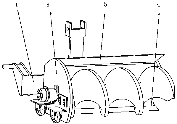
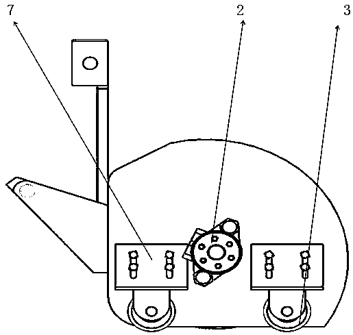
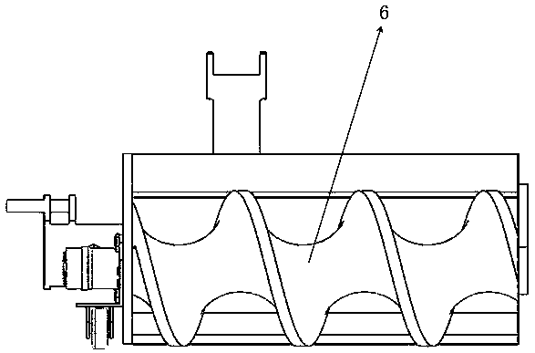
[0024] The machine includes a screw pushing auger, a hydraulic motor part, a body casing, a pushing plate located at the lower part of the body casing, auxiliary wheels and a connecting device with a tractor. When working, the whole machine is placed on the front or back of the tractor, and the whole machine is driven by the tractor. The machine part is driven by the hydraulic motor on the left side of the fuselage to rotate the screw pusher auger to push the far feed to the cow trough, which is convenient for the cows to eat. The push plate at the bottom of the fuselage is made of rubber material to ...


PUM


Abstract

The invention relates to a spiral pushing type cow feed pushing robot and a feed pushing method. The feed pushing robot comprises a traveling device and a body shell connected with the traveling device through a connecting device and is characterized in that a spiral feed pushing auger extending towards the side where cows are located is arranged in the body shell; the body shell comprises a backplate whose extension direction is consistent to the extension direction of the spiral feed pushing auger and a lateral plate fixedly connected to one side, away from the cows, of the back plate, theback plate is located on one side, close to the traveling device, of the spiral feed pushing auger, and a hydraulic motor for driving the spiral feed pushing auger to rotate is fixedly arranged on thelateral plate. The spiral pushing type cow feed pushing robot has the advantages that the body shell and the auger of the robot are simple and practical in structure and convenient in mechanical manufacturing, and large-scale industrial manufacturing can be performed; one end and the front side of the auger are open, so that mounting and maintenance are facilitated; the feed pushing efficiency isincreased greatly as compared with that traditional manual feed pushing, and the problems of excessive residual feed, feed loss, manpower consumption and labor increasing caused by the manual feed pushing can be effectively reduced.

Description

technical field [0001] The invention relates to the technical field of animal husbandry tools, in particular to a screw push type milk cow pushing robot and a pushing method. Background technique [0002] In many pastures, the spreader cannot guarantee that all the feed it puts in is close to the fence during the spreading process, and some of the feed is far away from the cowshed after being put in, which leads to the fact that the cattle cannot reach it and affect their normal eating. As a result, problems such as feed loss and reduced dry matter intake of dairy cows directly affect the economic benefits of pastures. [0003] In traditional pastures, the feed is manually pushed into the fence, which will inevitably increase the labor cost in the production process, reduce the efficiency of cattle feeding, increase the amount of labor, and cause a waste of human, material and financial resources. The slow speed can easily lead to insufficient feed intake of dairy cows, and...

Claims


Application Information

Patent Timeline
IPC IPC(8): A01K5/00
CPCA01K5/00
Inventor 田富洋吴永政王中华宋占华闫银发李法德师科荣
Owner SHANDONG AGRICULTURAL UNIVERSITY
Learn More