Mold, shell and manufacturing method of texture on curve shell

A manufacturing method and mold technology, which is applied in the fields of electrical equipment shells/cabinets/drawers, telephone structures, telephone communications, etc., can solve the problems of affecting texture quality, difficult processing, and high equipment requirements, so as to reduce the difficulty of mold processing and reduce the Small processing difficulty, guaranteed texture quality effect

Pending Publication Date: 2020-01-21
深圳市山本光电股份有限公司
View PDF0 Cites 1 Cited by
  • Summary
  • Abstract
  • Description
  • Claims
  • Application Information

AI Technical Summary

Problems solved by technology

[0002] For the shell with curved surface structure, when designing the mold, it is necessary to set the male mold to the corresponding curved surface structure, so that the required curved surface shell can be made through the injection molding process. To form the corresponding texture on the curved surface shell, usually Process the corresponding texture structure on the curved surface of the male mold core, so that the corresponding texture can be formed on the curved surface of the curved shell after injection molding, but this method is difficult to process and requires high equipment (requires multi-axis linkage). The texture structure processed on the curved surface is prone to interference defects, which affects the texture quality of the shell after molding

Method used


Image

  • Mold, shell and manufacturing method of texture on curve shell
  • Mold, shell and manufacturing method of texture on curve shell
  • Mold, shell and manufacturing method of texture on curve shell

Examples


Embodiment 1

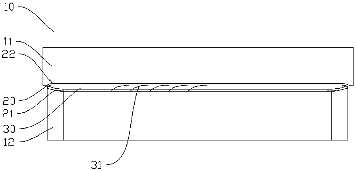
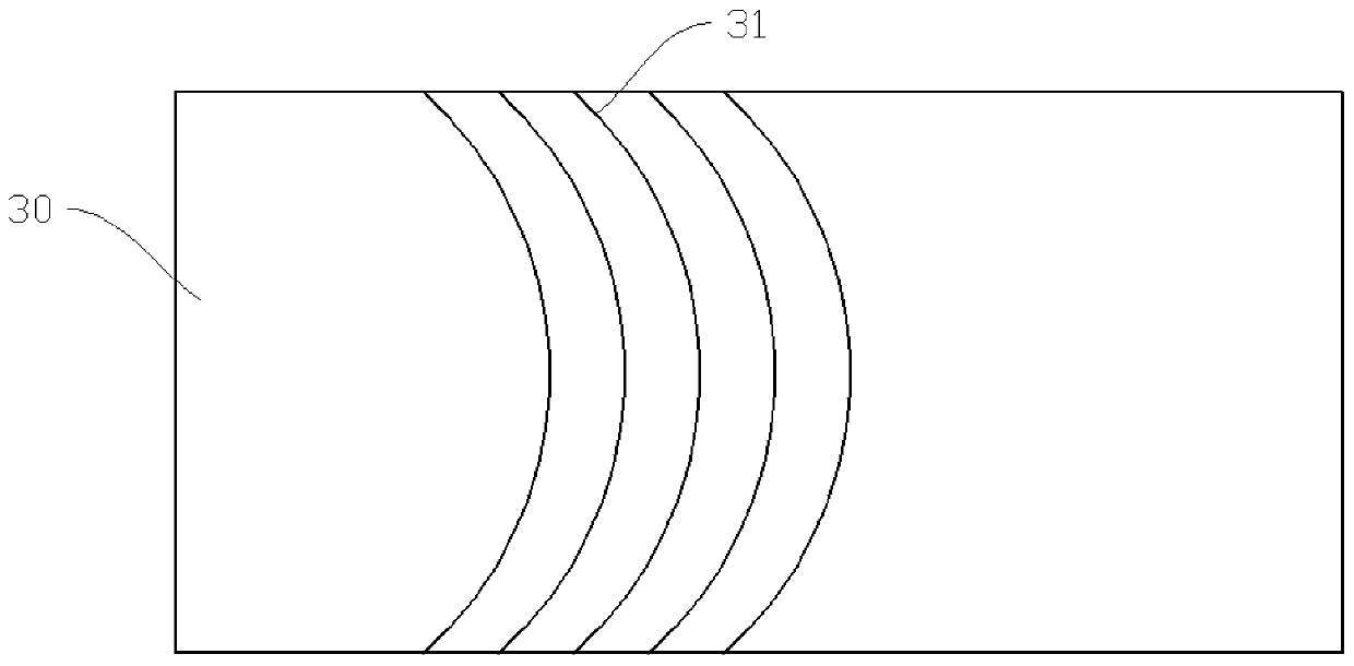
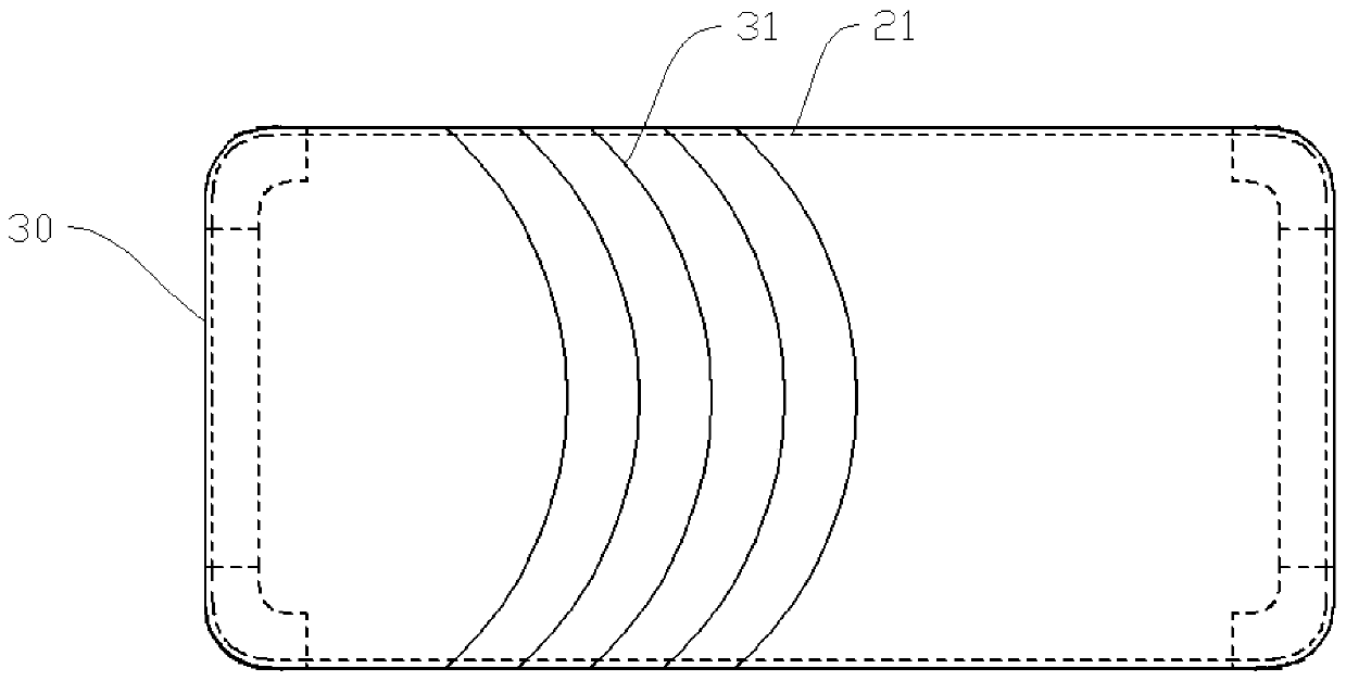
[0032] figure 1 It is a schematic diagram of an embodiment of the mold core of the present invention, figure 2 is a schematic diagram of one embodiment of an insert, image 3 It is a schematic diagram of an embodiment of the first core, please also refer to Figures 1 to 3 , the mold of this embodiment includes a mold core 10, the mold core 10 is provided with a cavity 20 for forming a shell with a curved surface, the first molding surface 21 of the cavity 20 is a curved surface structure, and is used for forming the shell on the shell. surface. Moreover, an insert 30 is detachably arranged on the first molding surface 21. The insert 30 is flexible and can be attached on the first molding surface 21 according to the shape of the curved surface structure of the first molding surface 21. The insert 30 faces A textured structure 31 is provided on one side surface of the cavity 20, so that textures can be formed on the curved surface of the casing after molding.

[0033] To m...

Embodiment 2

[0043] Figure 4 It is a schematic flow chart of the first embodiment of the method for manufacturing the texture on the curved shell, refer to Figure 4 , the manufacturing method of the texture on the curved shell of the present embodiment is: injection molding through a mold, wherein a first molding surface for molding the curved surface on the shell is set in the cavity of the mold, and the first molding surface is first formed on the first molding surface An insert with a textured structure and flexible attachment capability is attached, the textured structure of the insert faces the cavity, and then the mold is closed and injected, and the texture on the curved surface of the shell is formed by the textured structure at the corresponding position on the insert.

[0044] The following is the general process of the manufacturing method of the texture on the curved shell of this embodiment:

[0045] Manufacture of inserts: use sheet metal materials to make metal sheets, an...

Embodiment 3

[0052] Figure 5 It is a schematic flow chart of the second embodiment of the method for manufacturing the texture on the curved shell, refer to Figure 5 , the method of this embodiment is basically the same as the method of the above-mentioned second embodiment, including the processes of manufacturing the insert, attaching the insert, and injection molding, and the difference lies in the way of manufacturing the insert. The method of manufacturing the insert in this embodiment is to form the insert 30' through the metal powder injection molding process, roughly as follows: first process the texture groove 42 on the plane mold core 41 of the metal injection mold 40, and the metal powder and the metal powder during the molding process Under the action of the injection machine, the texture groove 42 of the metal injection mold 40 is integrally formed with the main body of the cavity to form a textured metal sheet, which is the required insert 30', and the texture structure on ...


PUM


Abstract

The invention relates to the technical field of electronic devices, and discloses a mold, a shell and a manufacturing method of a texture on a curve shell. The mold comprises a mold core, the mold core is provided with a cavity, a first forming face of the cavity is of a curve structure, and is used for forming a curve face on the shell, the first forming face is detachably provided with an embedded part, the embedded part is flexible and can be attached to the first forming face according to the shape of the curve structure of the first forming face, a texture structure is arranged on the surface of the side, facing the cavity, of the embedded part, the embedded part is attached to the curve forming face, mold assembly injection molding is carried out, the texture on the curve shell is formed after demolding of the position corresponding to the texture structure, through the mold, the texture on the curve shell and the shell body are subjected into injection molding into a whole, andthe curve shell with the texture can be formed. The procedure of machining the texture structure on the curve forming face of the mold core can be omitted, the texture machining difficulty on the curve shell can be reduced, and the texture forming quality is ensured.

Description

technical field [0001] The invention relates to the field of electronic devices, in particular to a mold, a shell and a method for manufacturing textures on the curved shell. Background technique [0002] For the shell with curved surface structure, when designing the mold, it is necessary to set the male mold to the corresponding curved surface structure, so that the required curved surface shell can be made through the injection molding process. To form the corresponding texture on the curved surface shell, usually Process the corresponding texture structure on the curved surface of the male mold core, so that the corresponding texture can be formed on the curved surface of the curved shell after injection molding, but this method is difficult to process and requires high equipment (requires multi-axis linkage). The texture structure processed on the curved surface is prone to interference defects, which affects the texture quality of the shell after molding. Contents of...

Claims


Application Information

Patent Timeline
Patent Type & Authority Applications(China)
IPC IPC(8): B29C45/14B29C45/26B29C45/17H04M1/02H05K5/00
CPCB29C45/14B29C45/26B29C2045/14237H04M1/0202H05K5/00
Inventor 王祥国杨利平
Owner 深圳市山本光电股份有限公司
Why Eureka
Try Eureka