
Differential type optical addressing potential sensor

A potential sensor and sensor technology, applied in the field of biochemical sensors, can solve the problems of complicated replacement and debugging operations, cumbersome measurement steps, and measurement results are easily affected by external factors, and achieve the effect of convenient replacement, easy replacement, and improved accuracy.

Active Publication Date: 2020-01-21
NORTHWESTERN POLYTECHNICAL UNIV
View PDF6 Cites 0 Cited by
  • Summary
  • Abstract
  • Description
  • Claims
  • Application Information

AI Technical Summary

Problems solved by technology

[0005] In order to overcome the shortcomings of the existing differential optical addressable potential sensor, which are cumbersome in measurement steps, complex in replacement and debugging, and easily affected by external factors, the present invention proposes a differential optical addressable sensor using a semiconductor device as a reference sub-sensor. Potential sensor

Method used


Image

  • Differential type optical addressing potential sensor
  • Differential type optical addressing potential sensor
  • Differential type optical addressing potential sensor

Examples


Embodiment Construction

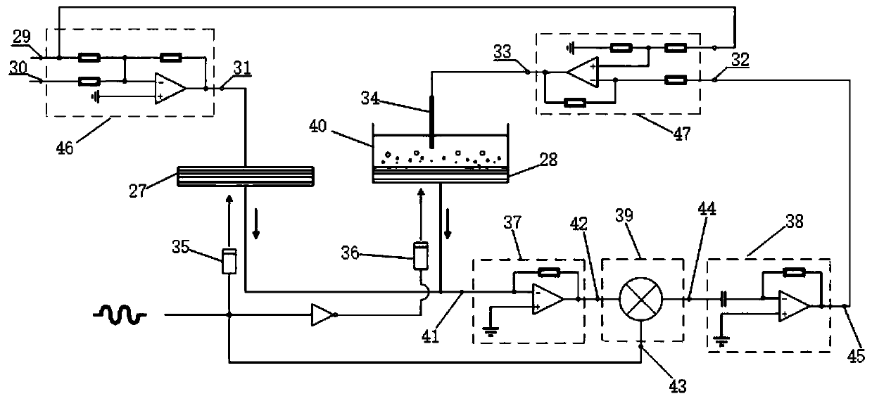
[0018] Refer to the following examples figure 2 , image 3 and Figure 4 .

[0019] Differential optical addressable potential sensor, including measurement sub-sensor 27, reference sub-sensor 28, measurement reference electrode 34, reference end laser 35, measurement end laser 36, current-voltage conversion circuit 37, integrator 38, phase-sensitive rectification circuit 39, adding circuit 46, subtracting circuit 47, solution pool 40.

[0020] The reference sub-sensor 27 is a semiconductor substrate in the shape of a square card. The thickness of the reference sub-sensor 27 is between 100-400um. The reference sub-sensor uses silicon nitride sensitive to hydrogen ions as the sensitive layer 19 , silicon dioxide as the transition layer 20 , and silicon as the semiconductor layer 21 . The cross-sectional structure of the reference sub-sensor is a metal electrode 18 - a sensitive layer 19 - a transition layer 20 - a semiconductor layer 21 - an output electrode 22 . The man...


PUM


Abstract

The invention discloses a differential type optical addressing potential sensor. The differential type optical addressing potential sensor is characterized in that a semiconductor device is used as areference sub-sensor, and the cross-section structure of the semiconductor device is a five-layer structure of a metal electrode, a sensitive layer, a transition layer, a semiconductor layer and an output electrode. A reference solution does not need to be added into the reference sub-sensor during measurement, so that the measurement step is simplified; the reference sub-sensor and a measurementsub-sensor are arranged on silicon wafers which are not connected with each other, so that the replacement of the differential type optical addressing potential sensor is facilitated; the reference sub-sensor is controlled by superposition of bias voltage and reference voltage, output photocurrent is prevented from being influenced by external factors, and the accuracy of the differential type optical addressing potential sensor is improved.

Description

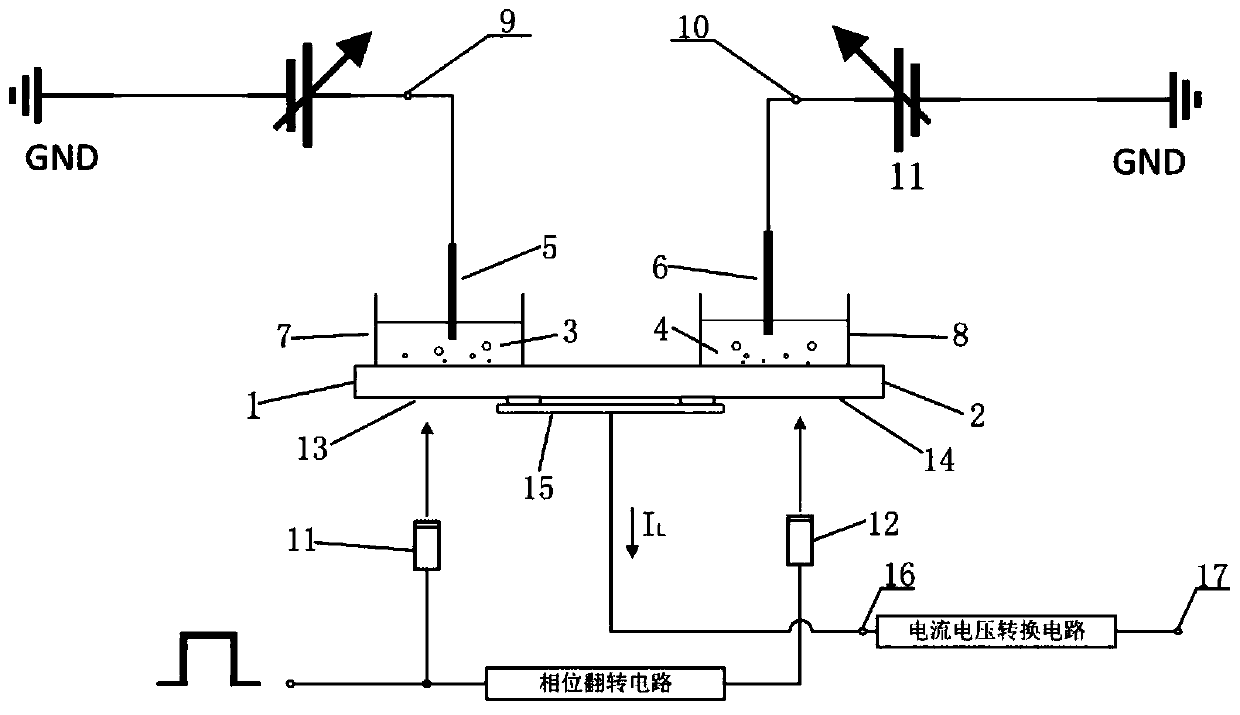
technical field [0001] The patent invention relates to the field of biochemical sensors, in particular to a differential optical addressing potential sensor. Background technique [0002] Photoaddressable potentiometric sensor is a kind of biochemical sensor with good performance. The differential optical addressable potential sensor consists of two single solution pool optical addressable potential sensors with a differential structure. The differential optical addressable potential sensor has the characteristics of low background noise and high precision. How to reduce sensor operation steps, improve measurement efficiency, and enhance sensor stability are technical problems that need to be solved urgently for differential optical addressable potential sensors. [0003] refer to figure 1 , Document 1 "A novel low-noise measurement principle for LAPS and its application to faster measurement of pH" discloses a differential photo-addressable potential sensor with a dual s...

Claims


Application Information

Patent Timeline
IPC IPC(8): G01N27/26G01N27/30
CPCG01N27/26G01N27/305G01N27/307
Inventor 刘诗斌罗杰璋
Owner NORTHWESTERN POLYTECHNICAL UNIV
Learn More