
Integrated single-laser-source optical device for movable cold atom interferometer

An optical device and interferometer technology, which is applied to devices for controlling the output parameters of lasers, lasers, phonon exciters, etc., can solve the problems of complex devices, limited application scope, large size, etc., and achieves improved ease of adjustment and stability. The effect of reducing the complexity, simplifying the optical path structure

Inactive Publication Date: 2020-01-21
NAT INNOVATION INST OF DEFENSE TECH PLA ACAD OF MILITARY SCI
View PDF1 Cites 13 Cited by
  • Summary
  • Abstract
  • Description
  • Claims
  • Application Information

AI Technical Summary

Problems solved by technology

Although this method of using multiple semiconductor laser sources combined with an optical phase-locked loop can achieve the required laser frequency and power, the device is still relatively complex, bulky, expensive, and poor in stability; also achieved based on two (Zhang X , Zhong J, Tang B, Chen X, Zhu L, Huang P, Wang J, Zhan M Applied Optics 2018, 57, 6545; O. Carraz, F. Lienhart, R. Charrière, M. Cadoret, N. Zahzam, Y .Bidel, A.Bresson, Appl.Phys.B, 97, 405-411, 2009)) and 1 (Theron F, Carraz O, Renon G, Zahzam N, BidelY, Cadoret M, Bresson A Applied Physics B 2014, 118,1; Luo Q, Zhang H, Zhang K, DuanXC, Hu ZK, Chen LL, Zhou MK Rev Sci Instrum 2019, 90, 043104) Fiber Optics Device for Fiber Laser Source in 1.5μm Communication Band
Although the development of 1.5μm laser sources and fiber optic devices is relatively mature, the complex, inefficient, expensive, and high-power laser frequency doubling modules limit the application range of 1.5μm frequency doubling fiber laser optical devices, and the frequency doubling scheme Only applicable to atoms such as rubidium and potassium, not applicable to other types of alkali metal atoms

Method used


Image

  • Integrated single-laser-source optical device for movable cold atom interferometer
  • Integrated single-laser-source optical device for movable cold atom interferometer
  • Integrated single-laser-source optical device for movable cold atom interferometer

Examples


Embodiment Construction

[0034] The present invention will be further described in detail below in conjunction with the accompanying drawings and specific embodiments.

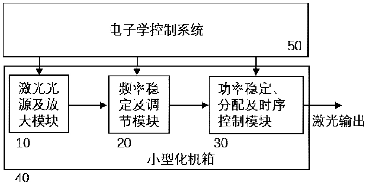
[0035] Such as figure 1 As shown, the integrated single laser source optical device for the movable cold atom interferometer of the present invention includes:

[0036] Laser source and power amplification module 10, used to generate single-frequency laser;

[0037] The laser frequency stabilization and adjustment module 20 is used to convert the single-frequency laser into the seven laser frequencies required by the cold atom interferometer;

[0038] Laser power stabilization, distribution and timing control module 30, used to generate various lasers of specific frequency and power in time sequence;

[0039] The microwave source and electronic control module 50 are used for switching and timing control of all the above modules, and the final output light is transmitted to the sensor head module of the atom interferometer through fo...


PUM


Abstract

The invention discloses an integrated single-laser-source optical device for a movable cold atom interferometer, and the device comprises a laser source and a power amplification module which are usedfor generating single-frequency laser; a laser frequency stabilizing and adjusting module which is used for converting the single-frequency laser into seven laser frequencies required by the cold atom interferometer; a laser power stabilization, distribution and time sequence control module which is used for generating various lasers with specific frequency and power according to a time sequence;and a microwave source and electronics control module which is used for carrying out switching and time sequence control on all the modules, wherein the final output light is transmitted to the sensing head module of the atomic interferometer through the four polarization maintaining optical fibers. The device has the advantages of small volume, low power consumption, low cost, high stability andthe like.

Description

technical field [0001] The invention mainly relates to the technical field of cold atom interference precision measurement, in particular to an integrated single laser source optical device for a movable cold atom interferometer. Background technique [0002] The cold atom interferometer is a new generation of high-precision measuring instruments that use atomic matter waves instead of light waves as the measurement medium. Because cold atoms have the characteristics of short de Broglie wavelength, long free evolution time, large static mass, small velocity distribution of atomic groups, and complex internal energy level structure, cold atom interferometry has many intrinsic advantages over laser interferometry in precision measurement. and good technical potential. According to the different directions and modes of interaction between laser and atoms, atomic interference gravimeters, gravity gradiometers, atomic interference gyroscopes, atomic clocks and other precision me...

Claims


Application Information

Patent Timeline
IPC IPC(8): H01S5/06H01S5/065H01S5/068H01S5/12
CPCH01S5/06H01S5/0657H01S5/068H01S5/12
Inventor 胡青青马明祥徐馥芳杨俊罗玉昆李莹颖强晓刚汪杰朱凌晓贾爱爱王亚宁李期学
Owner NAT INNOVATION INST OF DEFENSE TECH PLA ACAD OF MILITARY SCI
Learn More