A dual-wavelength anti-soldering equipment

A dual-wavelength, solder mask technology, applied in the field of PCB manufacturing, can solve the problems of uneven illumination, uneven exposure of solder mask ink, etc.

Active Publication Date: 2022-01-25
ZHONGSHAN AISCENT TECH
View PDF9 Cites 0 Cited by
  • Summary
  • Abstract
  • Description
  • Claims
  • Application Information

AI Technical Summary

Problems solved by technology

[0002] Solder-proof equipment is one of the equipment required for PCB manufacturing. In order to meet the functional requirements, dual-wavelength light sources are usually used. For solid-state laser light sources with shorter wavelengths, the monochromaticity and coherence are good. When using multi-mode fiber transmission, because Speckle, resulting in non-uniform illumination and thus non-uniform exposure of the solder resist ink during exposure

Method used


Image

  • A dual-wavelength anti-soldering equipment
  • A dual-wavelength anti-soldering equipment
  • A dual-wavelength anti-soldering equipment

Examples


Embodiment 1

[0060] Embodiment 1. Vibrating motor type speckle dissipation structure

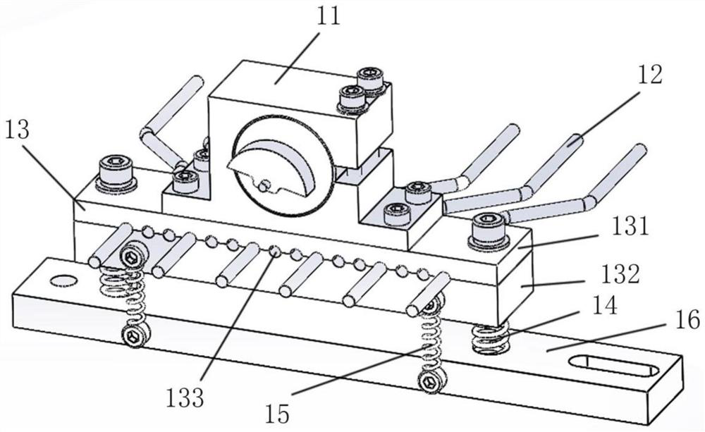
[0061] The vibration motor speckle dissipation structure of the illustrated embodiment includes: a vibration motor 11 , a multimode optical fiber 12 , an optical fiber clamping mechanism 13 , a damping spring and a fixing seat 1616 .

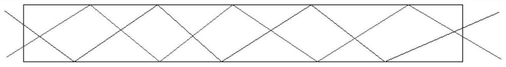
[0062] The vibration motor 11 is used as a vibration source. The vibration motor can adopt any existing vibration motor, as long as it can realize vibration. In one embodiment, the vibration motor has an eccentric wheel, and when the eccentric wheel rotates, it drives the entire motor to vibrate in the front-back and up-down directions. The frequency of vibration is achieved by adjusting or selecting the rotational speed of the vibration motor. Advantageously, the vibration motor 11 is an electric motor. During the entire working process of the dual-wavelength anti-soldering equipment, the vibration motor is operated to drive the multimode optical fiber 12 to always be ...

Embodiment 2

[0076] Embodiment 2. Linear Motion Dissipated Speckle Structure

[0077] The linear motion speckle dissipation structure of the embodiment shown in the figure includes: a driving motor 21 , a multimode optical fiber 22 , an optical fiber clamping mechanism 23 , a screw movement module, a fixing seat 26 and an origin sensor 27 .

[0078] The screw movement module includes a screw 24 and a linear slider 25 , and the linear slider 25 is provided with an internal thread matched with the screw 24 .

[0079] The driving motor 21 is installed on the fixing seat 26, and the screw rod 24 is driven to rotate forward and reverse repeatedly through the repeated forward and reverse rotation of the driving motor, and then the linear slider 25 is driven to reciprocate linearly along the axial direction of the screw rod 24 sports.

[0080] The multimode fiber 22 is the same as that of the first embodiment.

[0081] The optical fiber clamping mechanism 23 is basically the same in structure a...

Embodiment 3

[0086] Embodiment 3. Cam motion type speckle dissipation structure

[0087] The illustrated cam-type speckle dissipation structure includes: a driving motor 31 , a multimode optical fiber 32 , an optical fiber clamping mechanism 33 , a cam 34 , a linear slider 35 , a fixing seat 36 and a tension spring 37 .

[0088] working principle:

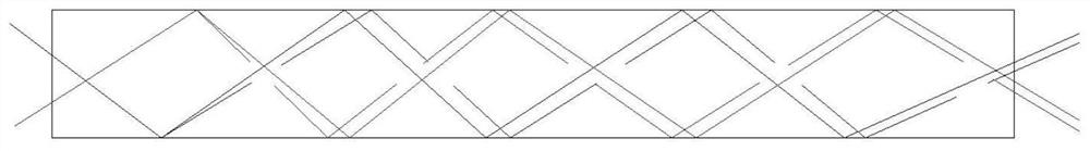
[0089] When the cam 34 is rotated by the driving motor 31, it drives the linear slider 35 to move linearly, so that the optical fiber clamping mechanism 33 and the multimode optical fiber 32 move together. The interior of the multimode fiber 32 moves forward and backward following the high and low points, thereby changing the position of the reflection point in the middle of the multimode fiber 32 , thereby changing the reflection point of the light beam inside the multimode fiber 32 . The cam 34 drives the linear slider 35 through contact transmission with two rollers.

[0090] The pull-back spring 37 ensures that when the cam 34 transitions...


PUM


Abstract

The invention discloses a dual-wavelength anti-soldering device. The dual-wavelength anti-soldering equipment includes: a dual-wavelength light source (900), a vibration unit (100), a multimode optical fiber (200) and a DMD digital micromirror (600), and the light beam emitted by the dual-wavelength light source (900) passes through multiple After the transmission of the mode fiber (200), the DMD digital micromirror (600) is used for imaging, and the dual-wavelength light source (900) includes light sources of two different wavelengths, wherein one light source is a 355nm pulse laser (901); the vibration unit ( 100) Imposing high frequency vibrations to said multimode optical fiber (200) at a middle section of said multimode optical fiber (200).

Description

technical field [0001] The invention relates to the technical field of PCB manufacturing, in particular to a dual-wavelength anti-soldering device. Background technique [0002] Solder-proof equipment is one of the equipment required for PCB manufacturing. In order to meet the functional requirements, dual-wavelength light sources are usually used. For solid-state laser light sources with shorter wavelengths, the monochromaticity and coherence are good. When using multi-mode fiber transmission, because Speckle, resulting in uneven illumination, which leads to uneven exposure of solder resist ink during exposure. Contents of the invention [0003] The object of the present invention is to provide a dual-wavelength solder resist device to improve the prevention of uneven exposure of solder resist ink during the exposure process. [0004] In order to achieve the above object, the present invention provides a dual-wavelength anti-soldering equipment. The dual-wavelength anti...

Claims


Application Information

Patent Timeline
Patent Type & Authority Patents(China)
IPC IPC(8): H05K3/28H05K3/06
CPCH05K3/28H05K3/06
Inventor 王瑞劳仲标梅文辉
Owner ZHONGSHAN AISCENT TECH
Why Eureka
Try Eureka