Atomizer for medical care

A nebulizer and atomization technology, applied in the field of medical care, can solve the problems of complex structure, dumping, cumbersome disassembly and assembly methods, and achieve the effect of simple disassembly and assembly methods, easy to rotate the chamber cover, and simple structure

Inactive Publication Date: 2020-01-24
李明磊
0 Cites 1 Cited by

AI-Extracted Technical Summary

Problems solved by technology

[0002] Medical nebulizers are mainly used to treat various upper and lower respiratory diseases. Nebulization inhalation therapy is an important and effective treatment method in the treatment of respiratory diseases. The nebulizer is used to atomize the liquid medicine into tiny particles, and the medicine passes through The method of inhalation enters the respiratory tract and lungs for deposition, so as to achieve the purpose of painless, rapid and effective treatment. The aerosol sprayed by the existing nebulizer contacts and accumulates on the piezoelectric material, making the aerosol easily polluted by heavy me...

Method used

Drainage assembly 6 comprises two sound insulation boards 61, and sound insulation board 61 can play the effect of noise reduction, reduces the noise of atomizer, and two sound insulation boards 61 are respectively arranged on the left and right sides of shell 1 inner wall, and shell The left and right sides of the inner wall of the body 1 and the top of the sound insulation board 61 are equipped with limit blocks 62, and the two sound insulation boards 61 are fixedly connected by a communication pipe 63, and the top of the upper communication pipe 63 is installed with a first threaded sleeve 64 , the bottom end of the liquid inlet pipe 5 communicates with the communication pipe 63, the surface of the liquid inlet pipe 5 is threaded with the first threaded sleeve 64, and the two adjacent communication pipes 63 are fixedly communicated through the liquid communication pipe 65, located below A liquid outlet pipe 66 is installed at the bottom of the connecting pipe 63 .
Please refer to Fig. 1-3, the present invention provides a kind of technical scheme: a kind of atomizer fo...

Abstract

The invention discloses an atomizer for medical care, including a shell and an atomizing cavity. The atomizing cavity is arranged at the top of the shell. As a drainage assembly and an atomizing assembly are arranged to cooperate with each other, a filter screen in the atomizing assembly can avoid the sprayed aerosol from contacting with and coating on a piezoelectric material and prevent the aerosol from being easily polluted by heavy metals. The structure is simple. Only the filter screen is needed to prevent the aerosol from being polluted. In actual use, the atomizer is easy to shake and even topple over when in use. Through the arrangement of the drainage assembly and since a plurality of communication pipes are arranged, the volume of the liquid medicine is greatly expanded, the volumetric difference with the volume of the whole atomizing cavity is reduced, and the liquid medicine in the atomizing cavity can be stably sucked instead of tipping and flowing out of a liquid medicinecavity. Meanwhile, the atomizer is convenient to maintain, and the disassembly and assembly mode in the maintenance process is relatively simple and time-saving and labor-saving, thus bringing greatconvenience to users.

Application Domain

Medical devicesMedical atomisers

Technology Topic

AerosolizeBiomedical engineering +10

Image

  • Atomizer for medical care
  • Atomizer for medical care
  • Atomizer for medical care

Examples

  • Experimental program(1)

Example Embodiment

[0019] The technical solutions in the embodiments of the present invention will be clearly and completely described below in conjunction with the accompanying drawings in the embodiments of the present invention. Obviously, the described embodiments are only a part of the embodiments of the present invention, rather than all the embodiments. Based on the embodiments of the present invention, all other embodiments obtained by those of ordinary skill in the art without creative work shall fall within the protection scope of the present invention.
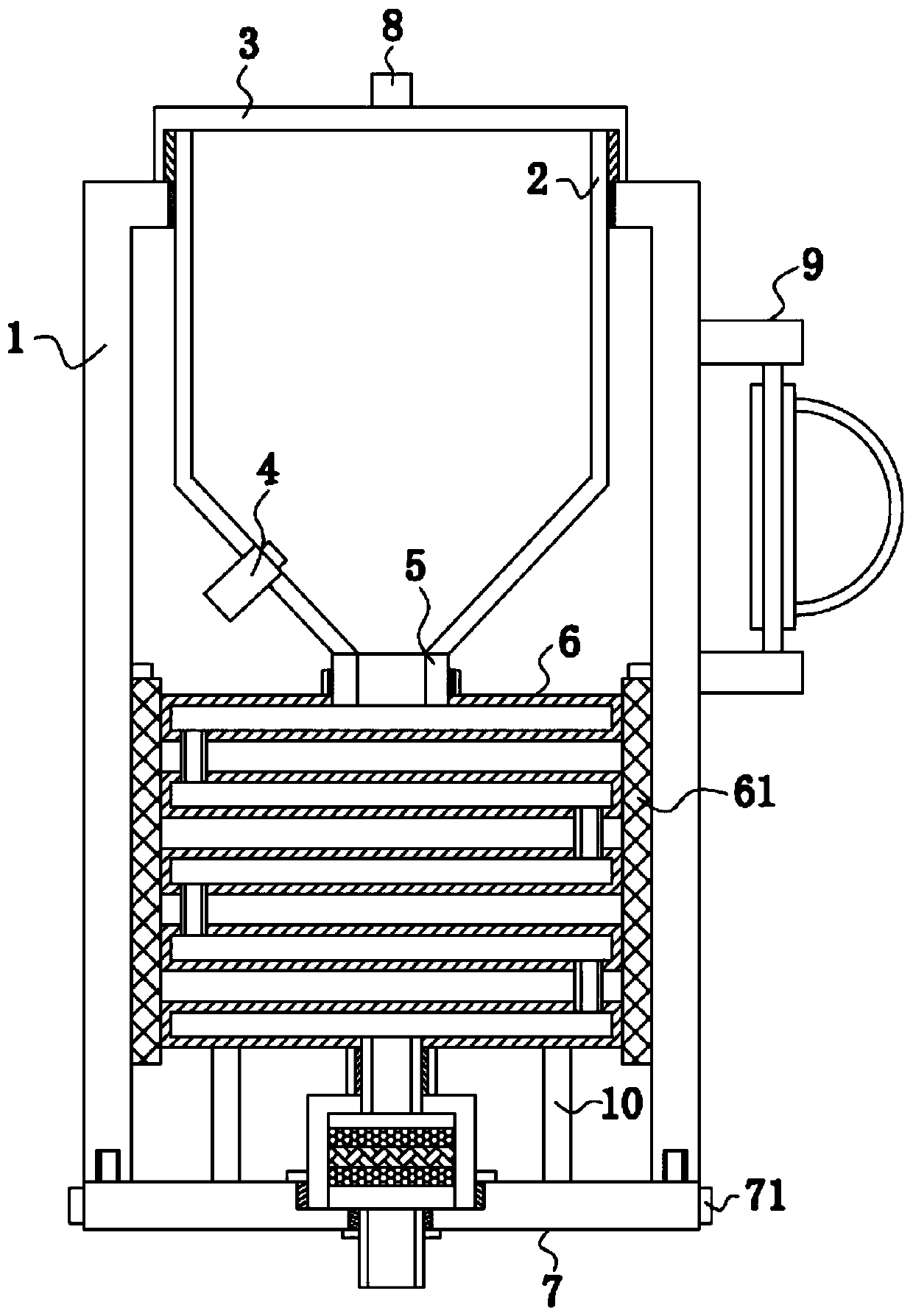
[0020] See Figure 1-3 , The present invention provides a technical solution: an atomizer for medical care, comprising a housing 1 and an atomization cavity 2. The atomization cavity 2 is arranged on the top of the housing 1, and the bottom of the atomization cavity 2 penetrates The housing 1 extends to the inside. A handle 9 is installed on the right side of the housing 1. The handle 9 is provided to facilitate carrying. The outer surface of the atomization cavity 2 is threaded with the housing 1, and the atomization cavity The top of 2 is screwed to the cavity cover 3, the top of the cavity cover 3 is equipped with a knob 8, and the surface of the knob 8 is provided with anti-slip patterns. The knob 8 and the anti-slip pattern cooperate with each other to facilitate the rotation of the cavity cover 3. A pressure pump 4 is installed at the bottom of the left side of the cavity 2, a liquid inlet pipe 5 is installed at the bottom of the atomization cavity 2, a drainage assembly 6 is installed at the bottom of the inlet pipe 5, and an atomization assembly 7 is installed at the bottom of the drainage assembly 6.
[0021] The drainage assembly 6 includes two sound insulation boards 61, which can reduce noise and reduce the noise of the atomizer. The two sound insulation boards 61 are respectively arranged on the left and right sides of the inner wall of the housing 1. Limiting blocks 62 are installed on the left and right sides of the sound insulation board 61 and located on the top of the sound insulation board 61. The two sound insulation boards 61 are fixedly connected by a connecting pipe 63. A first threaded sleeve 64 is installed on the top of the connecting pipe 63 on the upper side. The bottom end of the pipe 5 is in communication with the communicating pipe 63, the surface of the liquid inlet pipe 5 is threadedly connected with the first threaded sleeve 64, and the two adjacent communicating pipes 63 are fixedly communicated with each other through the liquid pipe 65, and the communicating pipe located below A liquid outlet pipe 66 is installed at the bottom of 63.
[0022] The atomization assembly 7 includes an atomization cover 71. A non-slip cover 11 is installed on the surface of the atomization cover 71. The non-slip cover 11 is provided to facilitate the opening of the atomization cover 71. A fixing cover 72 is installed on the top of the atomization cover 71. The top of the fixing sleeve 72 penetrates the casing 1 and extends to the inside. The outer surface of the fixing sleeve 72 is threadedly connected with the casing 1. The left and right sides of the top of the atomization cover 71 are installed with a limit rod 10, and the top of the limit rod 10 It is in contact with the communicating tube 63, and the stop rod 10 is provided to stably support the drainage assembly 6. The top of the atomization cover 71 is provided with an atomization shell 73, and the bottom of the atomization shell 73 penetrates the atomization cover 71 and extends to Inside, the outer surface of the atomization shell 73 is threadedly connected with the atomization cover 71, the surface of the atomization shell 73 is installed with the first sealing ring 12, and the bottom of the first sealing ring 12 is in close contact with the atomization cover 71. A sealing ring 12 serves as a seal to prevent the liquid medicine from flowing out through the gap between the atomizing cover 71 and the atomizing shell 73. A second threaded sleeve 74 is installed on the top of the atomizing shell 73. The surface is threadedly connected with the outlet pipe 66. The bottom of the outlet pipe 66 communicates with the atomization shell 73. The bottom of the atomization cover 71 is provided with an atomization tube 75 communicating with the atomization shell 73. The surface is threadedly connected with the atomization cover 71, the surface of the atomization tube 75 is equipped with a second sealing ring 13, and the top of the second sealing ring 13 is fixedly connected with the atomization cover 71. The second sealing ring 13 is provided to prevent the liquid medicine from passing through The gap between the atomization tube 75 and the atomization shell 73 flows out. An atomization module 76 is installed on the inner wall of the atomization shell 73. The atomization module 76 includes a piezoelectric material 761 and a filter 762.
[0023] Working principle: When in use, turn the cavity cover 3 through the knob 8 to open the atomization cavity 2, and then add an appropriate amount of liquid medicine to the atomization cavity 2, and then seal the atomization cavity 2 through the cavity cover 3. The pressure pump 4 acts to increase the pressure in the atomizing cavity 2 so that the liquid medicine enters the communicating pipe 63 through the liquid inlet pipe 5, and then enters the atomizing shell through the communicating pipe 63, the liquid pipe 65 and the liquid outlet pipe 66 In 73, the liquid medicine enters the atomization tube 75 through the filter 762 and the piezoelectric material 761 in the atomization shell 73. The atomization tube 75 generates mist. The filter 762 in the atomization assembly 7 can avoid the sprayed aerosol The contact and accumulation on the piezoelectric material 761 makes the mist susceptible to heavy metal pollution. The structure is simple. Only the filter 762 can prevent the mist from being polluted. In actual use, the atomizer is prone to shaking during use. Even pouring, by setting the drainage assembly 6, the volume of the liquid medicine is greatly expanded due to the multiple connecting pipes 63, and the difference with the volume of the entire atomization cavity 2 is reduced, so that the liquid medicine in the atomization cavity 2 can be It can be inhaled stably and will not flow out of the liquid medicine cavity due to tipping. At the same time, the atomizer is easy to maintain. Rotate the atomization cavity 2 to separate the atomization cavity 2 from the housing 1. The first threaded sleeve 64 and The liquid inlet pipe 5 is separated, the atomization cavity 2 is taken out of the housing 1, and the atomization cover 71 is rotated through the non-slip sleeve 11, the atomization cover 71 is separated from the housing 1, and the second threaded sleeve 74 is separated from the liquid outlet pipe 66 , The atomization assembly 7 can be taken out of the housing 1, and then the drainage assembly 6 can be taken out of the housing 1. The disassembly and assembly method in the maintenance process is relatively simple, which saves time and effort, and brings great benefits to the user. convenient.
[0024] Although the embodiments of the present invention have been shown and described, those of ordinary skill in the art can understand that various changes, modifications, and substitutions can be made to these embodiments without departing from the principle and spirit of the present invention. And variations, the scope of the present invention is defined by the appended claims and their equivalents.

PUM

no PUM

Description & Claims & Application Information

We can also present the details of the Description, Claims and Application information to help users get a comprehensive understanding of the technical details of the patent, such as background art, summary of invention, brief description of drawings, description of embodiments, and other original content. On the other hand, users can also determine the specific scope of protection of the technology through the list of claims; as well as understand the changes in the life cycle of the technology with the presentation of the patent timeline. Login to view more.

Similar technology patents

Body condition measuring device

InactiveUS20050234351A1simple structure
Owner:DENSO CORP

Magnetic cooling apparatus and control method thereof

ActiveUS20130180263A1simple structure
Owner:SAMSUNG ELECTRONICS CO LTD

Dual-Drivetrain of Power-Assist Vehicle

InactiveUS20100181130A1enhance uphill momentumsimple structure
Owner:CHOU WEN CHENG

Classification and recommendation of technical efficacy words

  • Simple structure
  • increase volume

Sharing system for air-conditioning coat

InactiveCN107440179ASimple structureeasy to wear
Owner:QINGDAO HAIER AIR CONDITIONER GENERAL CORP LTD

Feeding device of sorter of batteries plate

InactiveCN101357717ASimple structurecooperate well
Owner:NANJING NORMAL UNIVERSITY

Emergency parachuting device and method for multiple-rotor unmanned aerial vehicle

InactiveCN103895870Aavoid aircraft crashSimple structure
Owner:SOUTH CHINA AGRI UNIV +1

Intragastric Volume-Occupying Device

InactiveUS20090259246A1increase volume
Owner:WL GORE & ASSOC INC

Foamed mechanical planarization pads made with supercritical fluid

InactiveUS7166247B2decrease solubilityincrease volume
Owner:MICRON TECH INC

Elastic hollow particles for annular pressure buildup mitigation

InactiveUS20100113310A1decrease annular pressureincrease volume
Owner:BP CORP NORTH AMERICA INC

Fan and fan frame thereof

ActiveUS20080247864A1increase volume
Owner:DELTA ELECTRONICS INC
Why Eureka
Try Eureka