Reverse flow inclined tube sedimentation tank

A technology of inclined tube sedimentation tank and sedimentation tank, which is used in sedimentation separation, flocculation/sedimentation water/sewage treatment, sedimentation tank, etc., can solve the problems of sludge discharge effect, sludge splash and other problems that affect the efficiency of sludge discharge. To achieve the effect of improving efficiency and effect, and ensuring the effect

Inactive Publication Date: 2020-01-24
甘肃泓泰环保工程有限公司
View PDF0 Cites 3 Cited by
  • Summary
  • Abstract
  • Description
  • Claims
  • Application Information

AI Technical Summary

Problems solved by technology

[0005] The purpose of the present invention is to solve the problem that when the existing sedimentation tank discharges the sludge at the bottom, it is easy to cause the sludge to splash due to the flow of water, which affects the efficiency of sludge discharge and the effect of sludge discharge. Reverse flow inclined tube sedimentation tank

Method used


Image

  • Reverse flow inclined tube sedimentation tank

Examples


Embodiment 1

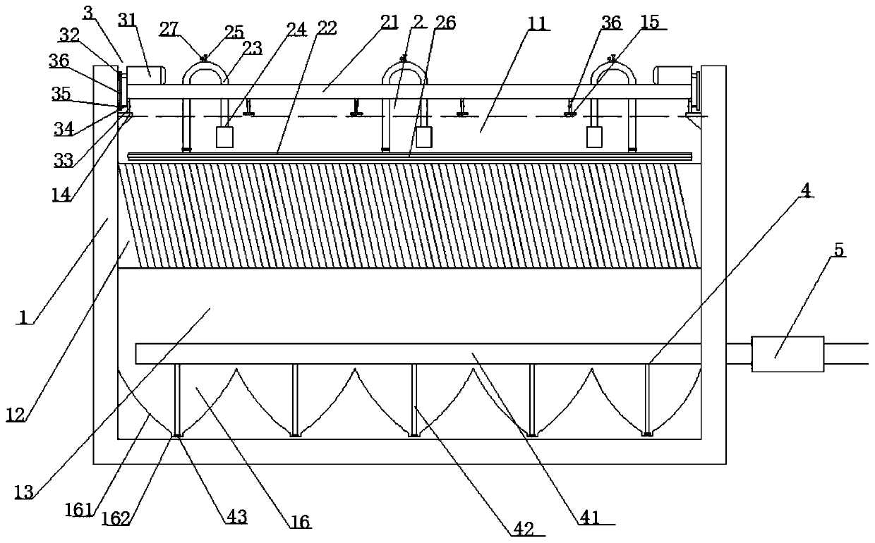
[0025] A reverse flow inclined tube sedimentation tank, comprising a sedimentation tank body 1, the sedimentation tank body 1 is sequentially provided with a mud sedimentation area 13, an inclined tube sedimentation area 12, and a water collection area 11 from bottom to top, and is characterized in that: The water collection area 11 is provided with a flushing device 2, and the bottom of the sedimentation area 13 has a plurality of sedimentation pits 16 in a rectangular array, and the edges of two adjacent sedimentation pits 16 are connected, and the sedimentation pits 16 include downward The arc-shaped ramp 161 and the downwardly recessed mud collection area 162 arranged at the bottom of the arc-shaped ramp 161, the slope of the arc-shaped ramp 161 gradually becomes smaller along the direction close to the mud collection area 162, and the mud pit 16 The top is provided with a mud discharge pipe 4, and the mud discharge pipe 4 includes a plurality of sets of mud discharge main ...

Embodiment 2

[0027] On the basis of Example 1, the flushing device 2 includes a support frame 21 whose length is the same as the width of the sedimentation tank body 1, and a cleaning main pipe 22 is arranged below the support frame 21, and the cleaning main pipe 22 is arranged along the cleaning main pipe. The length direction of 22 is provided with multiple sets of inverted U-shaped flushing pipes 23, one end of the U-shaped flushing pipes 23 is provided with a small submersible pump 24, and the middle section of the U-shaped flushing pipes 23 is provided with a manual ball valve 25 for adjusting pressure , the other end of the U-shaped flushing pipe 23 communicates with the cleaning main pipe 22, and the two sides of the cleaning main pipe 22 are provided with cleaning branch pipes 26. A low-pressure cleaning nozzle is provided, and the supporting frame 21 is provided with a moving mechanism 3 for moving the flushing device 2 back and forth along the length direction of the sedimentation...

Embodiment 3

[0029]On the basis of Embodiment 1 or 2, the moving mechanism 3 includes a variable frequency deceleration motor 31 arranged at both ends of the upper end surface of the support frame 21, and the output shaft of the variable frequency deceleration motor 31 is provided with a sprocket 1 32, and the support The two ends of the lower end surface of the frame 21 are provided with driving wheels 33, and the left and right side walls of the sedimentation tank body 1 above the water collection area 11 are provided with main slide rails 14 along the length direction of the sedimentation tank body 1. Drive wheel 33 can freely roll along the length direction of main slide rail 14 on main slide rail 14, and described drive wheel 33 center is provided with rotating shaft 34, and described rotating shaft 34 outer ends are fixedly connected with sprocket wheel 2 35, and described sprocket wheel Link by chain 36 between one 32 and sprocket two 35.


PUM


Abstract

The invention discloses a reverse flow inclined tube sedimentation tank. The reverse flow inclined tube sedimentation tank comprises a sedimentation tank body; a sludge settling zone, an inclined tubesettling zone and a water collecting zone which are communicated with one another are sequentially arranged in the sedimentation tank body from bottom to top; a flushing device is arranged in the water collecting zone; a plurality of mud settling pits are formed in the bottom of the sludge settling zone in a rectangular array; the edges of each pair of adjacent mud settling pits are connected; each mud settling pit comprises an arc-shaped ramp and a silt collecting zone arranged at the bottom of the arc-shaped ramp, the gradient of each arc-shaped ramp is gradually reduced in the direction close to the corresponding silt collecting zone; a sludge discharge pipeline is arranged above the mud settling pits; the sludge discharging pipeline comprises a plurality of groups of sludge discharging main pipes which are arranged above the mud settling pits in parallel along the length direction of the sedimentation tank body; sludge discharge branch pipes in one-to-one correspondence with the mud settling pits are arranged on the sludge discharging main pipes, sludge suction nozzles are arranged at sludge inlet ends of the sludge discharge branch pipes and are pressed against the inner bottoms of the mud collecting zones, one end of the sludge discharge pipeline extends out of the sedimentation tank body and is provided with a sludge discharge pump. According to the reverse flow inclined tube sedimentation tank, the sludge discharge efficiency and effect are improved, and the sewage treatment effect is ensured.

Description

technical field [0001] The invention relates to the technical field of domestic and industrial water supply and sewage treatment, in particular to a reverse flow inclined tube sedimentation tank. Background technique [0002] A sedimentation tank is a structure that uses sedimentation to remove suspended solids in water. Sedimentation tanks are widely used in wastewater treatment. [0003] Inclined tube sedimentation tank refers to a sedimentation tank with inclined tubes in the sedimentation area. The inclined tube sedimentation tank is divided into three different separation methods: reverse (different) flow, cocurrent flow and side flow according to their mutual movement directions. Between every two parallel sloping plates (or in parallel pipes) is equivalent to a very shallow sedimentation tank. The advantages of the inclined tube sedimentation tank are: ①Using the principle of laminar flow, the processing capacity of the sedimentation tank is improved; ②The particle...

Claims


Application Information

Patent Timeline
Patent Type & Authority Applications(China)
IPC IPC(8): B01D21/00B01D21/02B01D21/24B01D21/30C02F1/52
CPCB01D21/0006B01D21/0057B01D21/0069B01D21/02B01D21/245B01D21/30C02F1/52C02F2201/002C02F2209/005C02F2209/03C02F2303/14
Inventor 李泓
Owner 甘肃泓泰环保工程有限公司
Why Eureka
Try Eureka