In-situ centrifugal casting device and centrifugal casting method for thin-wall alloy castings with circular ring sections

An alloy casting and centrifugal casting technology, applied in the field of centrifugal casting equipment, can solve the problems of easy generation of cold insulation, air entrapment, low utilization rate of materials, hidden dangers to the safety of users, etc. The effect of eliminating the need for mechanical processing

Inactive Publication Date: 2020-01-24
HARBIN INST OF TECH
View PDF5 Cites 3 Cited by
  • Summary
  • Abstract
  • Description
  • Claims
  • Application Information

AI Technical Summary

Problems solved by technology

[0003] However, the traditional centrifugal casting process needs to be completed step by step through separate smelting equipment and centrifugal casting equipment. Generally speaking, it needs to be smelted in the smelting equipment, and then poured by transferring the melt to the centrifugal casting equipment. This process not only increases the cumbersomeness of the process, but also poses safety hazards to users during the transfer of the melt and the pouring process; at the same time, if the transfer of the melt takes a long time, there will be direct contact between the high-temperature melt and the air for a long time. A large amount of gas enters and partially oxidizes; in addition, due to the instability of the pouring speed during the pouring process, it is easy to produce cold shut and air entrainment; secondly, because the smelting equipment is separated, the possibility of inclusions in the alloy is also greatly increased Not only that, because this pouring process also needs to increase the corresponding sprue, which will bring more material waste in the sprue, resulting in low material utilization, and further machining is required after forming, increasing Big cost
[0004] In summary, in view of the potential safety hazards in the melt transfer and pouring process in traditional centrifugal casting, as well as the problems of cold shut, inclusions, pores and high cost, it is necessary to propose a new centrifugal casting equipment and method to improve Centrifugal casting process eliminates potential safety hazards to the human body during transfer of melt and pouring process to prevent the occurrence of these alloy defects, increase material utilization, reduce production costs, and improve production efficiency

Method used


Image

  • In-situ centrifugal casting device and centrifugal casting method for thin-wall alloy castings with circular ring sections
  • In-situ centrifugal casting device and centrifugal casting method for thin-wall alloy castings with circular ring sections
  • In-situ centrifugal casting device and centrifugal casting method for thin-wall alloy castings with circular ring sections

Examples


specific Embodiment approach 1

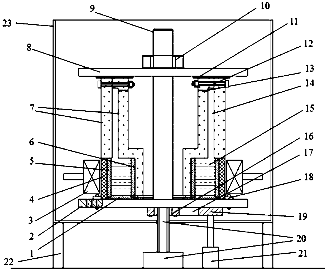
[0021] Specific Embodiment 1: The in-situ centrifugal casting equipment for thin-walled circular cross-section alloy castings in this embodiment includes an in-situ smelting system, a casting system, a limit fixing system, and a centrifugal rotation system; wherein, the in-situ smelting system includes graphite heaters, induction heating Coil 3 and heat preservation tube 4; casting mold system is casting mold 7; limit fixing system includes upper platen 8, limit guide post 9, axial limit nut 10 and chassis 2; centrifugal rotation system includes motor 21, driving wheel 19 , driven wheel 16, transmission belt 17; Described graphite heater is made up of graphite bottom ring 1, graphite outer cylinder 5 and graphite inner cylinder 6, and graphite inner cylinder 6 is positioned at graphite outer cylinder 5, and graphite outer cylinder 5 and graphite inner cylinder 6 is arranged on the graphite bottom ring 1 to form a circular cylindrical cavity, the alloy raw material 15 is put int...

specific Embodiment approach 2

[0027] Embodiment 2: This embodiment differs from Embodiment 1 in that the material of the insulation cylinder 4 is zirconia.

specific Embodiment approach 3

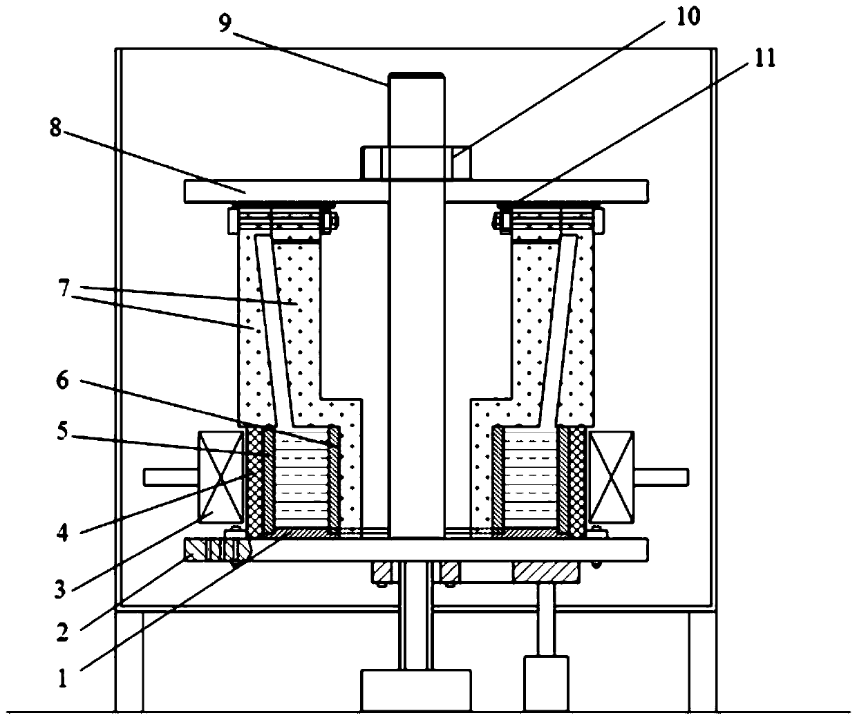
[0028] Specific embodiment three: the difference between this embodiment and specific embodiment one or two is that the cavity 14 of the mold 7 is a cylindrical cavity or a cone-shaped cavity, and the mold 7 is a two-half mold through the fixing bolts (12) CONNECTION.

[0029] In this embodiment, when the cavity of the mold is cone-shaped, the schematic diagram of the structure is as follows: figure 2 shown. The shape of the mold is matched with the shape of the casting.


PUM

PropertyMeasurementUnit
diameteraaaaaaaaaa

Abstract

The invention provides an in-situ centrifugal casting device and a centrifugal casting method for thin-wall alloy castings with circular ring sections, and relates to the centrifugal casting device and the centrifugal casting method for the alloy castings. The centrifugal casting device and the centrifugal casting method aim at optimizing tedious processes of traditional centrifugal casting, eliminating potential safety hazards during melt transferring and pouring, reducing defects such as casting cold shut, inclusion and pores, avoiding waste of alloys in pouring gates, improving the production efficiency and reducing cost. In the in-situ centrifugal casting device, alloy raw materials are loaded in a graphite heater fixed to a bottom plate, a heat preservation barrel is placed outside the heater, an induction heating coil is arranged outside the heat preservation barrel, a casting mold is arranged on the tops of the heater and the heat preservation barrel, a limiting guide column isfixed to the circle center position of the bottom plate, and by twisting an axial limiting nut, an upper pressing plate can be moved downwards to press all parts, between the upper pressing plate andthe bottom plate, together with the bottom plate. According to the in-situ centrifugal casting method, the alloy raw materials are molten in the centrifugal device, a mold cavity of the casting mold is full filled with the alloy raw materials under the effect of centrifugal force, the alloy raw materials are solidified and formed, and coupling of in-situ smelting and in-situ centrifugation is achieved.

Description

technical field [0001] The invention relates to centrifugal casting equipment and a centrifugal casting method for alloy castings. Background technique [0002] At present, for the forming of thin-walled cylindrical alloy castings, centrifugal casting technology is usually used because it has the characteristics of fast filling speed of molten metal and high feeding pressure. [0003] However, the traditional centrifugal casting process needs to be completed step by step through separate smelting equipment and centrifugal casting equipment. Generally speaking, it needs to be smelted in the smelting equipment, and then poured by transferring the melt to the centrifugal casting equipment. This process not only increases the cumbersomeness of the process, but also poses safety hazards to users during the transfer of the melt and the pouring process; at the same time, if the transfer of the melt takes a long time, there will be direct contact between the high-temperature melt an...

Claims


Application Information

Patent Timeline
Patent Type & Authority Applications(China)
IPC IPC(8): B22D13/04B22D13/10
CPCB22D13/04B22D13/10B22D13/101
Inventor 苏彦庆罗磊骆良顺王斌斌李志文王亮郭景杰刘振军李志平吕琦曹丙谦杜尧
Owner HARBIN INST OF TECH
Why Eureka
Try Eureka