Method for high-energy efficiency control over inlet and outlet electro-hydraulic position independent regulation servo system based on proportional overflow valve

An electro-hydraulic position servo, proportional relief valve technology, applied in servo motors, servo meter circuits, servo motor components, etc., can solve the problems of low pressure loss and heat generation, low energy efficiency of electro-hydraulic valve-controlled servo systems, etc. The effect of pressure loss, improving energy utilization efficiency and reducing overflow loss

Active Publication Date: 2020-01-24
TAIYUAN UNIV OF TECH
5 Cites 1 Cited by

AI-Extracted Technical Summary

Problems solved by technology

[0004] Aiming at the problem of low energy efficiency of the electro-hydraulic valve control servo system, the present invention provides an electro-hydraulic position servo system with low pressure loss, low...

Abstract

The invention discloses a method for high-energy efficiency control over an inlet and outlet electro-hydraulic position independent regulation servo system based on a proportional overflow valve. Theoverall control strategy is implemented through four sub-controllers, namely the position controller, the back pressure controller, the overflow pressure regulating controller and the pump flow controller. The position controller controls the flow of an oil inlet cavity of a hydraulic actuator through adjusting the position of a valve core of a servo valve I on the basis of a given position instruction and actual position feedback of the hydraulic actuator; the back pressure controller controls the pressure of an oil outlet cavity of the hydraulic actuator by adjusting the position of a valvecore of a servo valve II on the basis of the reference back pressure value and the actual back pressure cavity pressure of the hydraulic actuator; based on the pressure of the oil inlet cavity and thepressure drop on the valve I, the overflow pressure adjusting controller adjusts the proportional overflow valve online, and sets the oil source pressure of a hydraulic system in real time to reducethe pressure loss of a valve port; and by adjusting the rotating speed of a motor, the flow controller adjusts the flow output of a pump to be matched with the flow required by the system in real timeso as to reduce overflow flow loss.

Application Domain

Servomotor componentsServomotors +1

Technology Topic

Electric machineryServo +7

Image

  • Method for high-energy efficiency control over inlet and outlet electro-hydraulic position independent regulation servo system based on proportional overflow valve

Examples

  • Experimental program(1)

Example Embodiment

[0022] The specific embodiments of the present invention will be further described below with reference to the accompanying drawings, taking the actuator impedance extension working condition as an example.
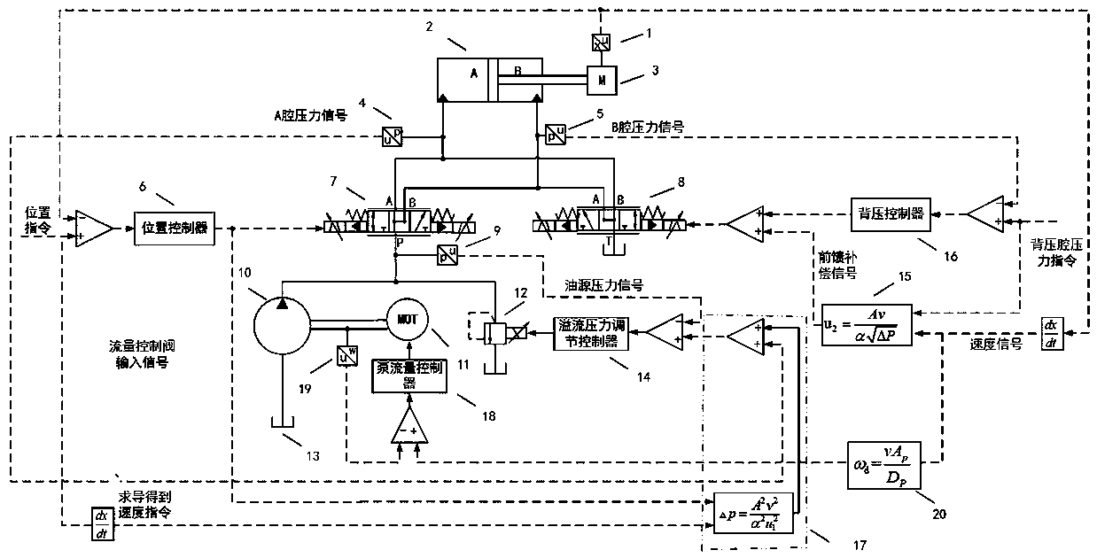
[0023] As shown in the figure, the electro-hydraulic position servo system for independent adjustment of the inlet and outlet based on the proportional relief valve in the embodiment of the present invention includes a displacement sensor 1, a hydraulic actuator 2, a load 3, a first pressure sensor 4, and a second pressure sensor 5. Position controller 6, I servo valve 7, II servo valve 8, oil source pressure sensor 9, quantitative pump 10, servo motor 11, proportional relief valve 12, fuel tank 13, relief pressure adjustment controller 14, Feedforward compensator 15 , back pressure controller 16 , overflow pressure command planner 17 , pump flow controller 18 , angular velocity sensor 19 , rotational speed command planner 20 . The servo motor 11 is connected with the quantitative pump 10 through a coupling. The quantitative pump 10 is connected to the proportional relief valve 12 through a pipeline. The proportional relief valve 12 is connected to the oil tank 13 through a pipeline. The quantitative pump 10 is connected to the P port of the first servo valve 7 through a pipeline. The A port of the first servo valve 7 is connected with the A cavity of the hydraulic actuator 2 through the pipeline, and the B port is connected with the B cavity of the hydraulic actuator 2 through the pipeline. The A cavity of the hydraulic actuator 2 is connected to the B port of the second servo valve 8 through the pipeline, and the B cavity of the hydraulic actuator 2 is connected to the A port of the II proportional servo valve 8 through the pipeline. The T port of the second servo valve 8 is connected to the oil tank 13 . Each sensor of the system is respectively connected with each corresponding sensor signal processing device in the control system, and each controller in the control system applies the generated control instructions to the controlled elements of the corresponding subsystem respectively.
[0024] Referring to the accompanying drawings, the working principle of this embodiment is described in detail as follows:
[0025] 1. When the hydraulic actuator 2 is in the condition of resistance extension, the first servo valve 7 controls the flow rate of the oil inlet chamber A, and the second servo valve 8 controls the pressure of the oil outlet chamber B. The oil circuit of the system is as follows: the first servo valve 7 works in the left position, and the second servo valve 8 works in the left position. Hydraulic oil flows in from the P port of the first servo valve 7 , flows out from the A port, and flows into the A chamber of the hydraulic actuator 2 . On the other hand, the hydraulic oil flows out from the B chamber of the hydraulic actuator 2 , flows in from the A port of the second servo valve 8 , flows out from the T port, and finally flows into the oil tank 13 .
[0026] 2. The relief pressure regulating controller 14, the proportional relief valve 12 and the first pressure sensor 4 constitute the oil source pressure servo subsystem. The nonlinear pressure-flow equation uses the speed signal of the hydraulic actuator 2 and the output signal of the position controller 6 to calculate the pressure drop on the first servo valve 7 in real time, and then according to the pressure in the A chamber measured by the first pressure sensor 4 and the first I The calculated pressure drop of the servo valve 7 generates the oil source pressure command signal. The overflow pressure adjustment controller 14 uses the actual oil source pressure signal and the oil source command signal measured by the oil source pressure sensor 9 to realize the pressure closed-loop servo control, and sets the overflow pressure of the proportional relief valve 12 in real time, so that the quantitative pump 10 outputs The pressure of the hydraulic actuator matches the pressure required by the hydraulic actuator into the oil chamber A.
[0027]3. The position controller 6, the first servo valve 7 and the displacement sensor 1 constitute the position closed-loop servo subsystem. In the position closed-loop servo subsystem, the position controller 6 uses the actual position signal measured by the displacement sensor 1 and the given position command. The spool displacement of the first servo valve 7 is adjusted by the signal to realize the position closed-loop servo control.
[0028] 4. The back pressure controller 16, the second servo valve 8 and the second pressure sensor 5 constitute the back pressure chamber pressure servo subsystem. In the back pressure chamber pressure servo subsystem, the back pressure controller 16 is based on the back pressure chamber pressure command signal and the first II. The pressure sensor 5 detects the pressure signal of the oil outlet chamber B to generate a back pressure signal. The feedforward compensator 15 uses the speed signal of the hydraulic actuator 2 and the pressure command of the back pressure chamber according to the nonlinear pressure flow equation of the small hole throttling. The signal generates a feedforward compensation signal to suppress the influence of the flow change of the oil inlet chamber A on the pressure control of the oil outlet chamber B. The back pressure signal and the feedforward compensation signal jointly adjust the spool displacement of the second servo valve 8 to realize the pressure closed-loop servo control.
[0029] 5. The servo motor 11, the pump flow controller 18, and the angular velocity sensor form a flow servo subsystem. In the flow servo subsystem, the rotational speed command planner 20 uses the speed signal of the hydraulic actuator 2 to determine the area of ​​the hydraulic actuator 2 A p and quantitative pump 10 displacement D p Calculate and generate the rotational speed command signal of the motor; the pump flow controller 18 realizes the closed-loop servo control of the rotational speed of the servo motor 11 according to the rotational speed command signal and the actual rotational speed signal measured by the angular velocity sensor 19, and adjusts the rotational speed of the servo motor 11 in real time to make the flow rate output by the quantitative pump 10. match the flow required by the system.
[0030] The hydraulic actuator 2 in the above embodiment is an asymmetric cylinder, and a symmetric hydraulic cylinder or a hydraulic motor can also be used.
[0031] In the above embodiment, the speed signal of the hydraulic actuator 2 is generated by a position sensor plus a differentiator and a filter, and can also be obtained by installing a speed sensor.
[0032] The first servo valve 7 and the second servo valve 8 in the above embodiment are servo flow valves, and proportional flow valves can also be used.

PUM

no PUM

Description & Claims & Application Information

We can also present the details of the Description, Claims and Application information to help users get a comprehensive understanding of the technical details of the patent, such as background art, summary of invention, brief description of drawings, description of embodiments, and other original content. On the other hand, users can also determine the specific scope of protection of the technology through the list of claims; as well as understand the changes in the life cycle of the technology with the presentation of the patent timeline. Login to view more.

Similar technology patents

Clock hand-off circuit

ActiveUS20110128052A1high precision
Owner:ADVANTEST CORP

Classification and recommendation of technical efficacy words

  • small pressure loss
  • High precision

Water-carrying domestic appliance having a water-distribution mechanism

ActiveUS8915257B2small pressure losslow delivery rate
Owner:BSH BOSCH & SIEMENS HAUSGERAETE GMBH

Air conditioning thin register

InactiveUS20160009163A1small pressure lossventilation resistance
Owner:TOYODA GOSEI CO LTD

Multiple spiral dust collector

InactiveCN1548245AReduce flow path resistancesmall pressure loss
Owner:LG ELECTRONICS (TIANJIN) APPLIANCES CO LTD

Method for forecasting short-term power in wind power station

InactiveCN102102626AHigh precision
Owner:NORTH CHINA ELECTRIC POWER UNIV (BAODING) +1

Numerical control machine tool wear monitoring method

InactiveCN102091972AHigh precisionReal-time monitoring of tool wear
Owner:HUAZHONG UNIV OF SCI & TECH +1

Advertisement recommendation method and apparatus

ActiveCN104965890AHigh precisionPrecise screening
Owner:SHENZHEN TENCENT COMP SYST CO LTD
Why Eureka
Try Eureka