Concrete stress testing system under high temperature and high pressure
A stress test, high temperature and high pressure technology, applied in the direction of applying stable tension/pressure to test the strength of materials, measuring devices, instruments, etc., can solve the inconvenience of providing a variety of complex environmental variables and the inability to achieve high temperature and high pressure variable adjustment control , Inconvenient transducer installation and other problems, to achieve the effect of convenient and quick height adjustment, saving test cost, and convenient for multiple use
- Summary
- Abstract
- Description
- Claims
- Application Information
AI Technical Summary
Problems solved by technology
Method used
Image

Examples
Embodiment 1
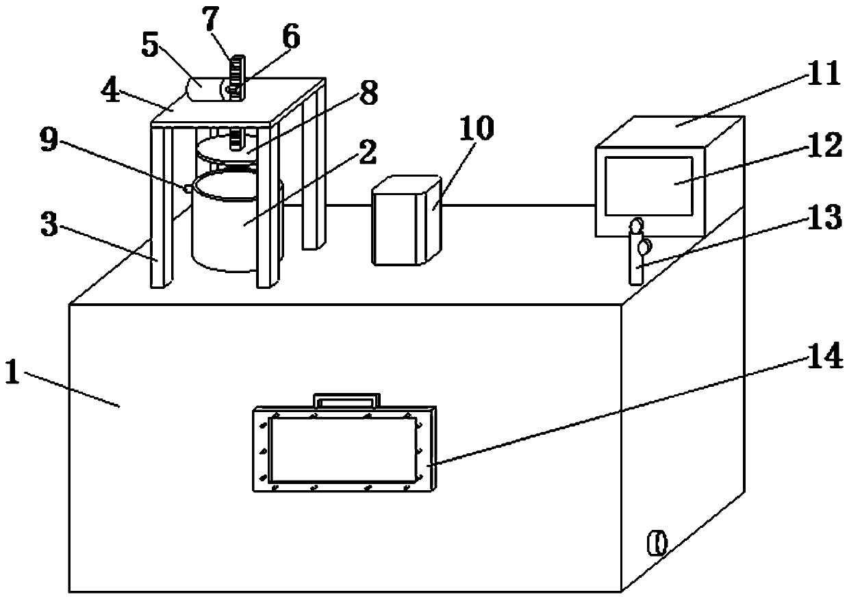
[0032] Such as Figure 1-3 and Figure 6 As shown, a concrete stress test system under high temperature and high pressure includes a main body box 1, a booster device, a stamping device, a sealed door structure, a temperature increase device and a control system. The booster device is installed on the upper side of the main body box 1, The stamping device is installed in the middle of the main box 1, the airtight door structure is installed in the front end of the main box 1, and the heating device is installed in the inner bottom outer surface of the main box 1;
[0033] The pressurization device includes a liquid inlet tank 2, which is connected to one end of the upper side of the main body box 1, and one side of the liquid inlet tank 2 is connected to a liquid inlet 9, which is close to the main body box 1 around the liquid inlet tank 2 Four groups of support rods 3 are fixedly installed, and top plates 4 are fixedly installed on the upper ends of the four groups of suppor...
Embodiment 2
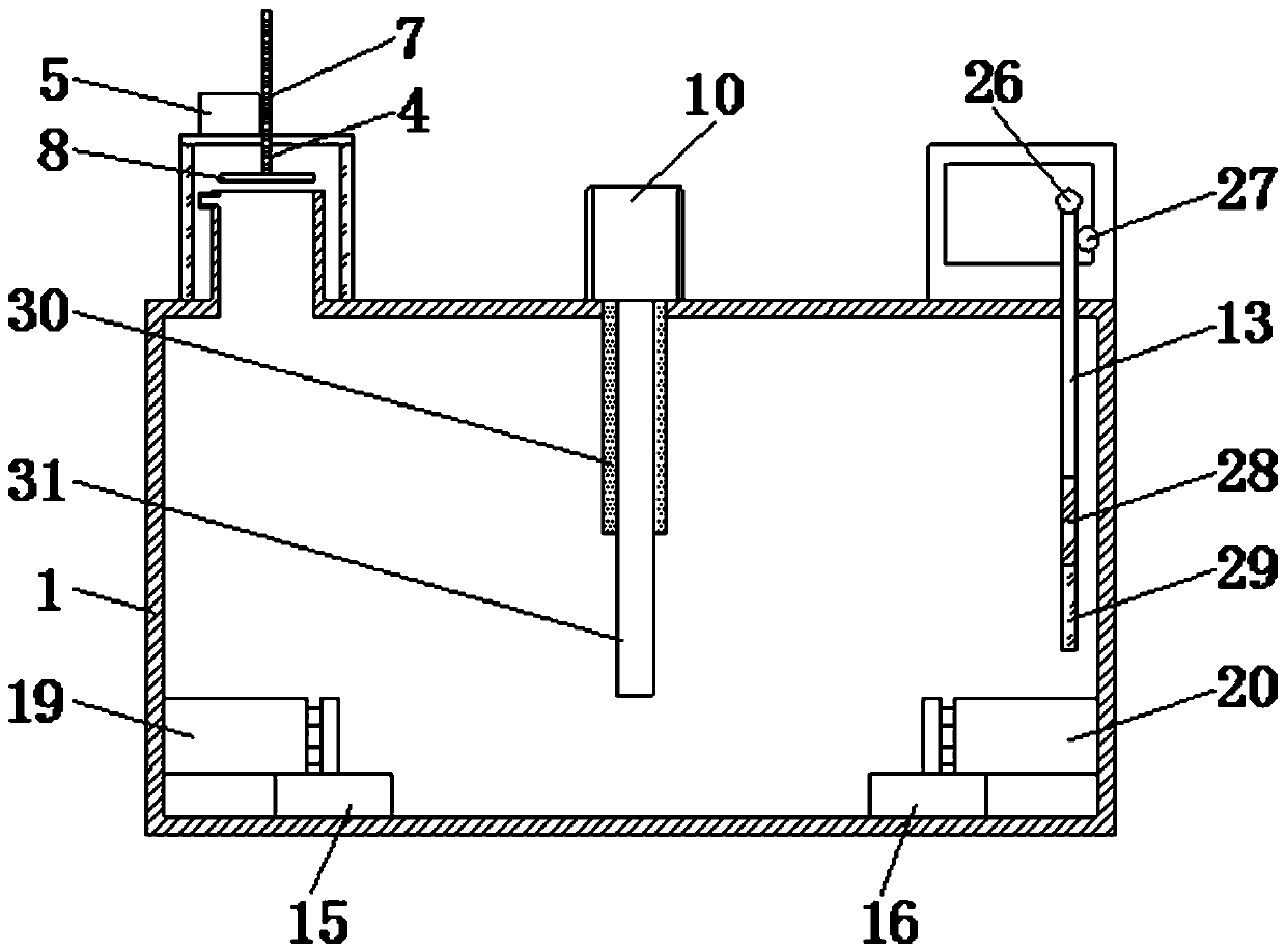
[0042] Such as Figure 1-6 As shown, a concrete stress test system under high temperature and high pressure includes a main body box 1, a booster device, a stamping device, a sealed door structure, a temperature increase device and a control system. The booster device is installed on the upper side of the main body box 1, The stamping device is installed in the middle of the main box 1, the airtight door structure is installed in the front end of the main box 1, and the heating device is installed in the inner bottom outer surface of the main box 1;
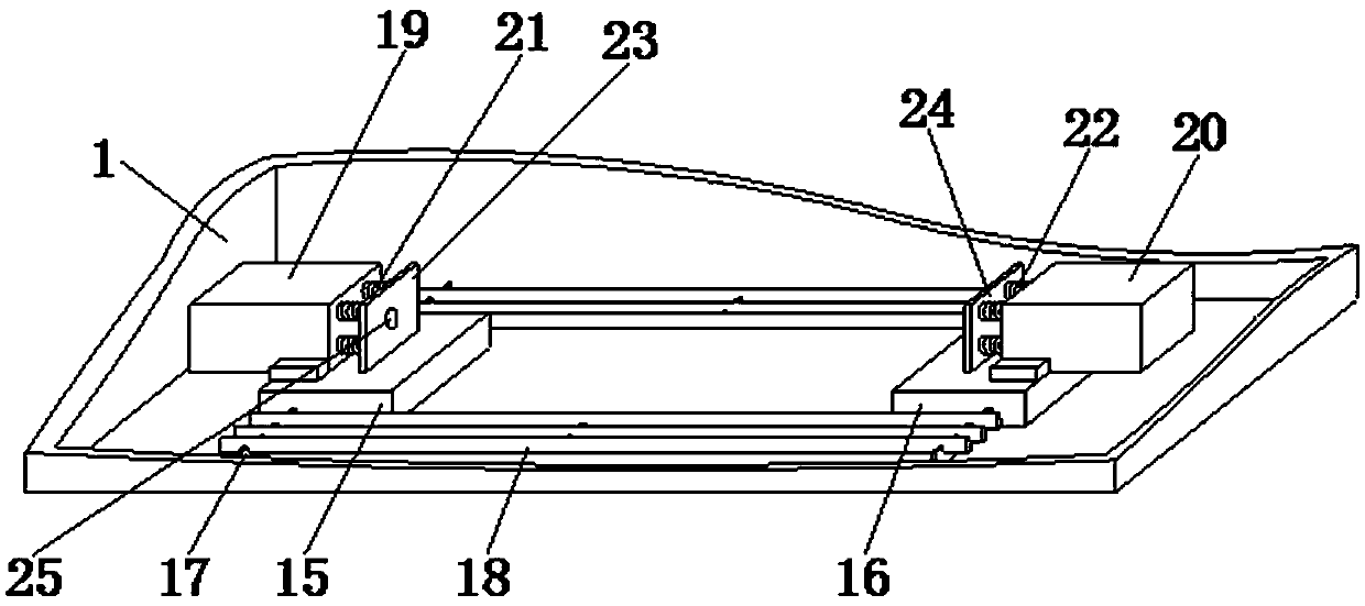
[0043] No. 1 sealing box 19 is fixedly installed on the upper end of No. 1 base plate 15, No. 2 sealing box 20 is fixedly installed on the upper end of No. 2 base plate 16, and four groups of No. 1 spring tubes 21 are fixedly installed on one side of No. 1 sealing box 19, four groups One side of No. 1 spring tube 21 is fixedly installed with No. 1 squeeze plate 23, one side of No. 2 sealed box 20 is fixedly equipped with four gro...
PUM
 Abstract
Description
Claims
Application Information
 - R&D
- Intellectual Property
- Life Sciences
- Materials
- Tech Scout
- Unparalleled Data Quality
- Higher Quality Content
- 60% Fewer Hallucinations
Browse by: Latest US Patents, China's latest patents, Technical Efficacy Thesaurus, Application Domain, Technology Topic, Popular Technical Reports.
© 2025 PatSnap. All rights reserved.Legal|Privacy policy|Modern Slavery Act Transparency Statement|Sitemap|About US| Contact US: help@patsnap.com