Supercharge Your Innovation With Domain-Expert AI Agents!

Truss teaching experiment device and experiment method based on photoelasticity

An experimental method and technology of an experimental device, which are applied in the field of truss teaching, can solve the problems of difficult to visually compare the rigid frame and the truss, the cumbersome process of pasting strain gauges, and the difficulty in measuring the axial force of the truss. Easy and convenient effect

Inactive Publication Date: 2020-01-24
BEIJING UNIVERSITY OF CIVIL ENGINEERING AND ARCHITECTURE
View PDF4 Cites 0 Cited by
  • Summary
  • Abstract
  • Description
  • Claims
  • Application Information

AI Technical Summary

Problems solved by technology

Generally, the truss structure teaching instruments use the electrical measurement method, and rarely use the optical measurement method, because the truss is in a unidirectional stress state, and the stress of the materials at each point is equal, and the direct truss model does not show in the light field of the photoelastic instrument. It is not easy to measure the axial force of the truss with the photoelastic method
However, the process of pasting the strain gauges by the electrical measurement method is cumbersome and difficult for students to operate, and the electrical measurement method can only measure the stress of individual measuring points, and it is impossible to observe the whole field, especially it is difficult to make an intuitive comparison between the rigid frame and the truss

Method used


Image

  • Truss teaching experiment device and experiment method based on photoelasticity
  • Truss teaching experiment device and experiment method based on photoelasticity
  • Truss teaching experiment device and experiment method based on photoelasticity

Examples


Embodiment 1

[0031] A truss teaching experimental device and experimental method based on photoelasticity, comprising the following steps:

[0032] S1. Arrangement of the light field of the photoelastic instrument:

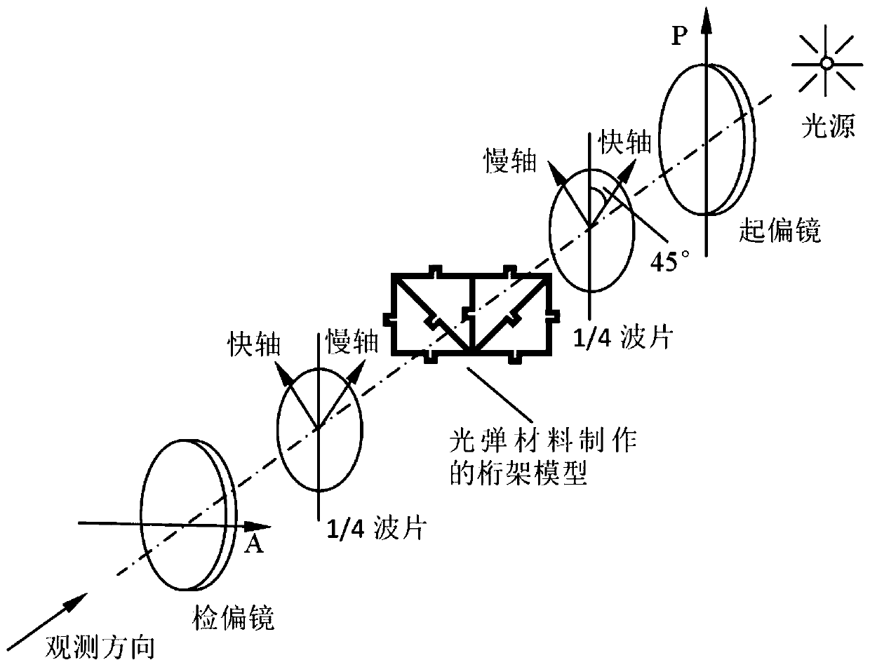
[0033] Select the photoelastic instrument and workbench, place the photoelastic instrument on the workbench, and place a computer for monitoring the work of the photoelastic instrument and a monitor matching the computer on the workbench. The electrical connection forms the light field of the photoelasticity meter; the photoelasticity meter uses a circularly polarized light field to eliminate isoclines and observe contour lines. The light path diagram under the circularly polarized light field is as follows: figure 1 shown.

[0034] S2. Making of truss model:

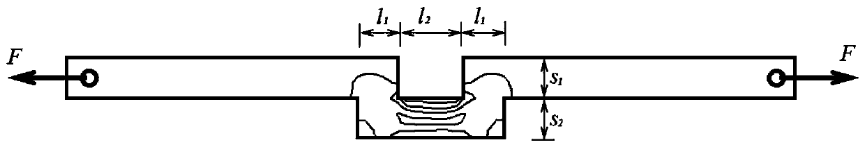
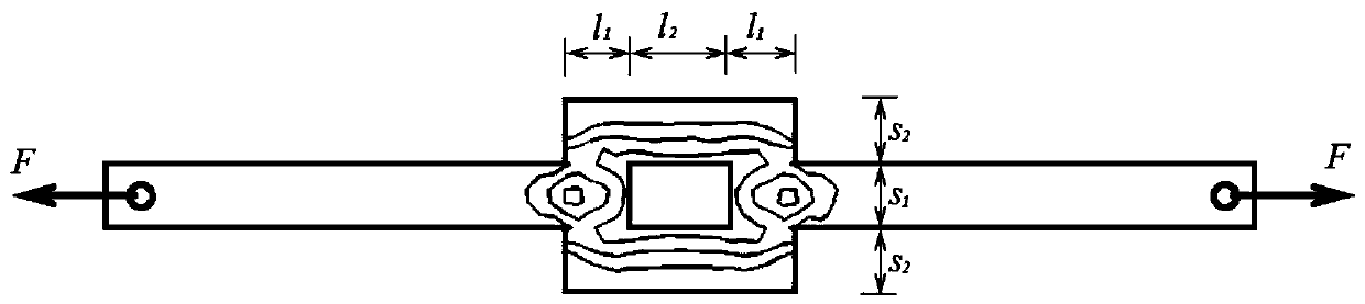
[0035] Since the rods in the truss structure are in a unidirectional stress state, and the stress difference at each point of the material is equal, the directly fabricated model cannot display contour lines when pla...

Embodiment 2

[0049] A truss teaching experimental device and experimental method based on photoelasticity, comprising the following steps:

[0050] S1. Arrangement of the light field of the photoelastic instrument:

[0051] Select the photoelastic instrument and workbench, place the photoelastic instrument on the workbench, and place a computer for monitoring the work of the photoelastic instrument and a monitor matching the computer on the workbench. The electrical connection forms the light field of the photoelasticity meter; the photoelasticity meter uses a circularly polarized light field to eliminate isoclines and observe contour lines. The light path diagram under the circularly polarized light field is as follows: figure 1 shown.

[0052] S2. Making of truss model:

[0053] Since the rods in the truss structure are in a unidirectional stress state, and the stress difference at each point of the material is equal, the directly fabricated model cannot display contour lines when pla...


PUM


Abstract

The invention discloses a truss teaching experiment device and an experiment method based on photoelasticity. The method comprises the following steps: arranging an optical field of a photoelastic instrument; fabricating a truss model with an eccentric component; carrying out experiment, namely, placing the truss model in the optical field of the photoelastic instrument, applying force to the truss model by using a loading mechanism, acquiring isodiff stripes of the truss model through the optical field of the photoelastic instrument, shooting and capturing the evolution of the stripes by utilizing a vidicon, and processing the photoelastic image through computer program, wherein the axial force of the truss is calculated according to the series of the stripes, direct comparison with a theoretical value is carried out, a zero bar in the truss structure can be intuitively observed, a force transferring path can be intuitively observed, and the relation and differences between a rigid frame and the truss can be intuitively observed; and carrying out analysis of the experiment data and experiment teaching. According to the technical scheme, the teaching on the aspect of stress analysis and the like of the truss can be carried out on students through the optical measurement method, and applying and popularizing are favorably carried out.

Description

technical field [0001] The invention relates to the technical field of truss teaching, in particular to a photoelastic-based truss teaching experimental device and experimental method. Background technique [0002] It is used in the experimental teaching of structural mechanics, theoretical mechanics and other courses. Generally, the truss structure teaching instruments use the electrical measurement method, and rarely use the optical measurement method, because the truss is in a unidirectional stress state, and the stress of the materials at each point is equal, and the direct truss model does not show in the light field of the photoelastic instrument. It is difficult to measure the axial force of the truss by the photoelastic method. However, the process of pasting the strain gauges by the electrical measurement method is cumbersome, and it is not easy for students to operate, and the electrical measurement method can only measure the stress of individual measuring points...

Claims


Application Information

Patent Timeline
IPC IPC(8): G09B23/10
CPCG09B23/10G06N3/08G06N3/045
Inventor 彭培火
Owner BEIJING UNIVERSITY OF CIVIL ENGINEERING AND ARCHITECTURE
Features
  • R&D
  • Intellectual Property
  • Life Sciences
  • Materials
  • Tech Scout
  • Unparalleled Data Quality
  • Higher Quality Content
  • 60% Fewer Hallucinations
Learn More