Floor-sweeping-capable duster equipment used in thermal power plant

A technology for thermal power plants and dust collectors, applied in the fields of smoke removal, fire rescue, chemical instruments and methods, etc., can solve the problems of difficult dust adsorption, waste of resources, low fire extinguishing efficiency, etc., achieve good sweeping function, ensure cleanliness, Good dust removal effect

Inactive Publication Date: 2020-01-31
大唐东营发电有限公司
View PDF8 Cites 1 Cited by
  • Summary
  • Abstract
  • Description
  • Claims
  • Application Information

AI Technical Summary

Problems solved by technology

[0004] 1. The existing dust collector only absorbs the dust in the air. Generally, it is difficult to absorb the dust adsorbed on the ground. As a result, there is still a lot of dust on the ground in the machine room. The effect of dust removal is not very good, and it is easy to be caused by dust. In the event of a short circuit in an electrical component
[0005] 2. The existing dust collector only has the function of dust removal, and does not have the function of fire extinguishing. Low, and the number of fire extinguishers is large, which will cause a waste of resources

Method used


Image

  • Floor-sweeping-capable duster equipment used in thermal power plant
  • Floor-sweeping-capable duster equipment used in thermal power plant
  • Floor-sweeping-capable duster equipment used in thermal power plant

Examples


Embodiment 1

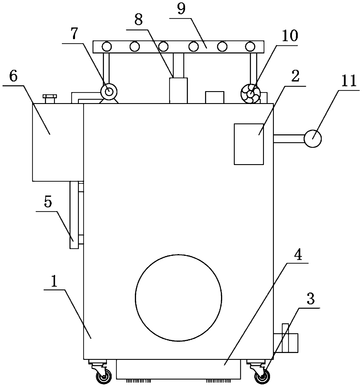
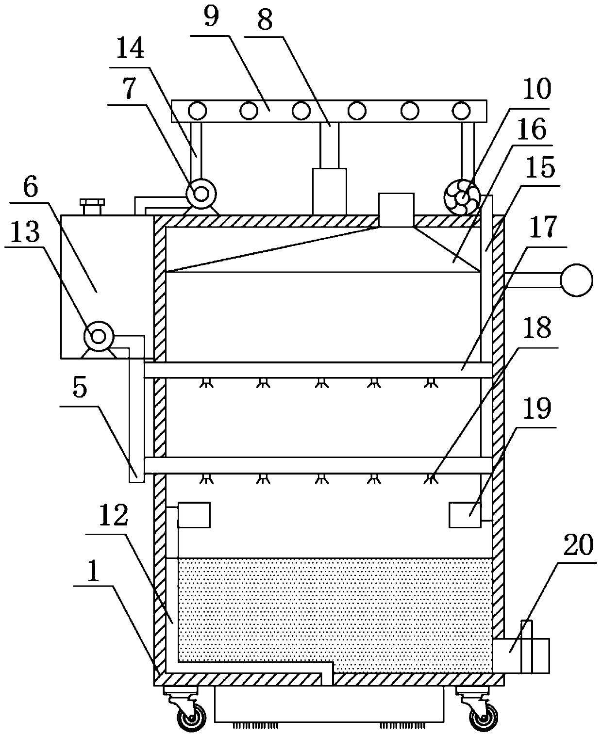
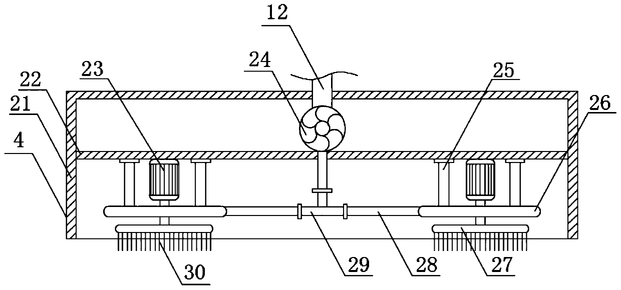
[0030] see Figure 1-6, the present invention provides a technical solution: a sweepable dust collector equipment for a thermal power plant, including a dust removal box 1, a controller 2 and a universal wheel 3, the controller 2 is fixedly installed on one side of the outer wall of the dust removal box 1, and the The universal wheel 3 is fixedly installed at the four corners of the bottom end of the dust removal box 1, and the bottom end of the dust removal box 1 is fixedly installed with a sweeping mechanism 4 inside the universal wheel 3, and the sweeping mechanism 4 includes a housing 21 and a partition 22. The casing 21 is fixedly mounted on the surface of the bottom end of the dust removal box 1, the partition 22 is welded inside the casing 21, the upper end of the partition 22 is fixedly installed with a No. 2 fan 24, and the outlet end of the No. 2 fan 24 is fixedly connected with two No. 2 air inlet pipe 12, the end of No. 2 air inlet pipe 12 away from the outlet end ...

Embodiment 2

[0037] see figure 1 , figure 2 , Figure 5 with Image 6 , the present invention provides a technical solution: a thermal power plant sweepable dust collector equipment, a water tank 6 is fixedly installed on one side of the outer wall of the dust removal box 1, and an electric telescopic is fixedly installed at the top of the dust removal box 1 close to the axis. Rod 8, the model of the electric telescopic rod 8 is TGA-100, the output end of the electric telescopic rod 8 is fixedly installed with a No. , and the No. 1 dust suction branch pipe 34 is provided with three groups, and one end of the No. 1 dust suction branch pipe 34 is fixedly equipped with a dust collection cover 36, and one side of the No. 1 dust suction main pipe 9 inner wall is fixedly installed with a water spray main pipe 33. One side surface of the water spray main pipe 33 is fixedly connected with a water spray branch pipe 35, one end of the water spray branch pipe 35 runs through the No. Water pump 7...


PUM


Abstract

The invention discloses a floor-sweeping-capable duster equipment used in a thermal power plant. The floor-sweeping-capable duster equipment comprises a dusting box, a controller and universal wheels;the controller is fixedly arranged on one side of the outer wall of the dusting box; the universal wheels are fixedly arranged on four corners of the bottom end of the dusting box; a floor-sweeping mechanism is arranged on a part, which is located on the inner sides of the universal wheels, of the bottom end of the dusting box; the sweeping mechanism comprises a shell and a separation plate; theshell is fixedly arranged on the surface of the bottom end of the dusting box; a very good dusting effect can be reached through the arranged floor-sweeping mechanism; dust floating in the air can becleared off, and dust adhered to the floor can also be cleaned; a very good sweeping function is provided; the very good dusting effect can be realized; cleanness of the environment in a machine roomis ensured; a water spraying header pipe is arranged, so that the duster equipment has a fire extinguishing function, and smoke generated during fire extinguishing can also be effectively reduced; injury to human bodies caused by smoke generated during fire extinguishing can be lowered; and the functionality of the duster equipment is greatly improved.

Description

technical field [0001] The invention relates to the technical field of thermal power plants, in particular to a sweepable dust collector equipment for thermal power plants. Background technique [0002] Thermal power plants, referred to as thermal power plants for short, are factories that use combustibles (such as coal) as fuel to produce electric energy. Its basic production process is: when the fuel is burned, the water is heated to generate steam, the chemical energy of the fuel is converted into thermal energy, the steam pressure drives the steam turbine to rotate, and the thermal energy is converted into mechanical energy, and then the steam turbine drives the generator to rotate, converting the mechanical energy into electrical energy. The prime mover is usually a steam engine or a gas turbine, and in some smaller plants, an internal combustion engine may also be used. They all generate electricity by using the pressure drop in the process of turning high-temperature...

Claims


Application Information

Patent Timeline
Patent Type & Authority Applications(China)
IPC IPC(8): B08B15/04B01D47/06B08B1/04B08B5/04A62C31/02
CPCA62C31/02B01D47/06B08B1/002B08B1/04B08B5/04B08B15/04
Inventor 李玮贾长武周恩浩田润平张忠兴
Owner 大唐东营发电有限公司
Why Eureka
Try Eureka