3D identification optical filter

A filter and 3D technology, applied in the field of optical filters, can solve the problems of increasing the number of filter film layers, widening the transition band, and deteriorating filter jitter, achieving high cut-off and narrow transition band width , the effect of small wavelength offset

Active Publication Date: 2020-01-31
FUZHOU PHOTOP QPTICS CO LTD
View PDF4 Cites 11 Cited by
  • Summary
  • Abstract
  • Description
  • Claims
  • Application Information

AI Technical Summary

Problems solved by technology

[0009] However, the existing 3D optical filter is based on the multi-cavity bandpass film system with high and low refractive indices as mentioned above, and there are still some problems: a) Si:H material has a strong absorption of light below 600nm wavelength, but There is no complete absorption of light in the 600-800nm ​​wavelength range, which makes it difficult for the filter to have a high cut-off in this range; b) further reducing the angle drift requires increasing the order of the cavity layer. In order to maintain the bandwidth of the passband, improve The number of cavity layers inevitably increases the mismatch between the optical cavities, resulting in poor jitter of the filter and widening of the transition band; c) Due to the influence of b), in order to maintain the jitter of the filter, it is necessary Significantly increase the number of cavities, resulting in a significant increase in the number of filter film layers, increasing the difficulty of preparation

Method used


Image

  • 3D identification optical filter
  • 3D identification optical filter
  • 3D identification optical filter

Examples


Embodiment Construction

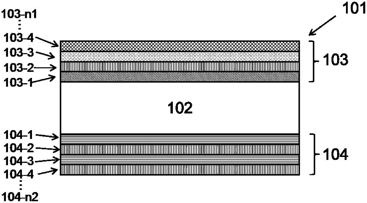
[0037] Such as figure 1 As shown, a 3D identification filter 101 according to the present invention includes a substrate 102, a filter layer 103 coated on one surface of the substrate 102, and a group of filter layers 104 coated on the other surface of the substrate 102. Floor. The substrate 102 transmits light to the working wavelength band of the optical filter, and plays a role of supporting the optical filter. Generally, when the passband of the filter is within the range of 800-1000nm, the substrate material is preferably optical glass with good light transmission, such as BK7, D263T, B270, etc. When the passband of the optical filter is near the 1550nm band, the substrate 102 can be selected as a silicon substrate. In particular, colored glass that has an absorption effect on a special wave band can also be used to achieve the purpose of further increasing the cut-off degree; by tempering the glass, the mechanical strength of the substrate can be further improved.

[...


PUM

PropertyMeasurementUnit
thicknessaaaaaaaaaa
refractive indexaaaaaaaaaa

Abstract

The invention discloses a 3D identification optical filter. The 3D identification optical filter is provided with a passband which is partially overlapped with a wavelength range of 800nm to 1800nm, and a cut-off band which comprises a range of 380nm to 750nm. The 3D identification optical filter comprises a substrate and optical filter film layers plated on two surfaces of the substrate, whereinthe optical filter film layer on one surface is formed by stacking a high refractive index layer, a medium refractive index layer and a low refractive index layer; and the optical filter film layer onthe other surface is formed by stacking at least two material layers. The 3D identification optical filter maintains a high cut-off degree and narrow transition band width while realizing small wavelength offset at a large light incident angle.

Description

technical field [0001] The invention relates to the field of optical filters, in particular to a 3D identification optical filter. Background technique [0002] Three-dimensional (3D) recognition technology has been widely used in fields such as machine vision, virtual reality, identity recognition, and automatic driving. Compared with two-dimensional imaging, 3D recognition can obtain the three-dimensional information of the detected object. The basic principle of 3D recognition is to emit infrared light of a certain band, and use the sensor to receive the light of this band returned by the detected object, and use signal processing to obtain distance information, thereby establishing a three-dimensional model of the detected object. The transmitter of a typical 3D recognition module includes an infrared light source, a modulation device, and a lens, and the receiver includes an infrared detector, lens, and infrared filter. [0003] For 3D recognition, the infrared filter...

Claims


Application Information

Patent Timeline
Patent Type & Authority Applications(China)
IPC IPC(8): G02B5/28C23C14/00C23C14/06C23C14/08C23C14/10C23C14/18C23C14/35C23C14/46
CPCG02B5/285C23C14/35C23C14/46C23C14/185C23C14/10C23C14/0652C23C14/0036C23C14/352C23C14/083C23C14/08C23C14/0057C23C14/0068C23C14/165C23C14/3442C23C14/505C23C14/548C23C14/3464G02B5/281C23C14/18
Inventor 刘哲于光龙李昱苏炎吴砺林志强
Owner FUZHOU PHOTOP QPTICS CO LTD
Why Eureka
Try Eureka