an artificial dielectric

A dielectric and artificial technology, applied in the direction of electrical components, mid-position feeding between antenna terminals, antennas, etc., can solve the problems of low resonant frequency, low upper limit, small adjustment range of relative permittivity, etc. The effect of high resonance frequency and wide adjustment range

Active Publication Date: 2021-10-01
WUTONG HLDG GRP CO LTD +1
View PDF1 Cites 0 Cited by
  • Summary
  • Abstract
  • Description
  • Claims
  • Application Information

AI Technical Summary

Problems solved by technology

[0008] In view of the fact that the existing artificial dielectrics with I-shaped and square-ring structures have a small adjustment range of relative permittivity, a low upper limit, and a low resonance frequency, the present invention proposes a method based on double-sided positive interdigitated fingers. The artificial dielectric surface of the strip structure has a higher resonant frequency than the existing I-shaped and square-ring artificial dielectrics, and a wider adjustable range of relative permittivity, which can meet the requirements of flexible regulation of electromagnetic waves in the application of higher microwave frequency bands. The specific technical solutions are as follows:

Method used


Image

  • an artificial dielectric
  • an artificial dielectric
  • an artificial dielectric

Examples


Embodiment 1

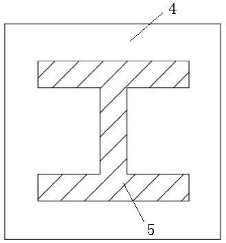
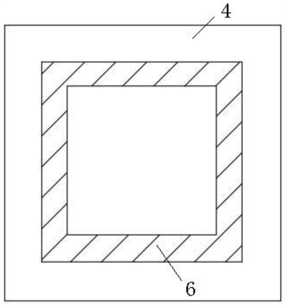
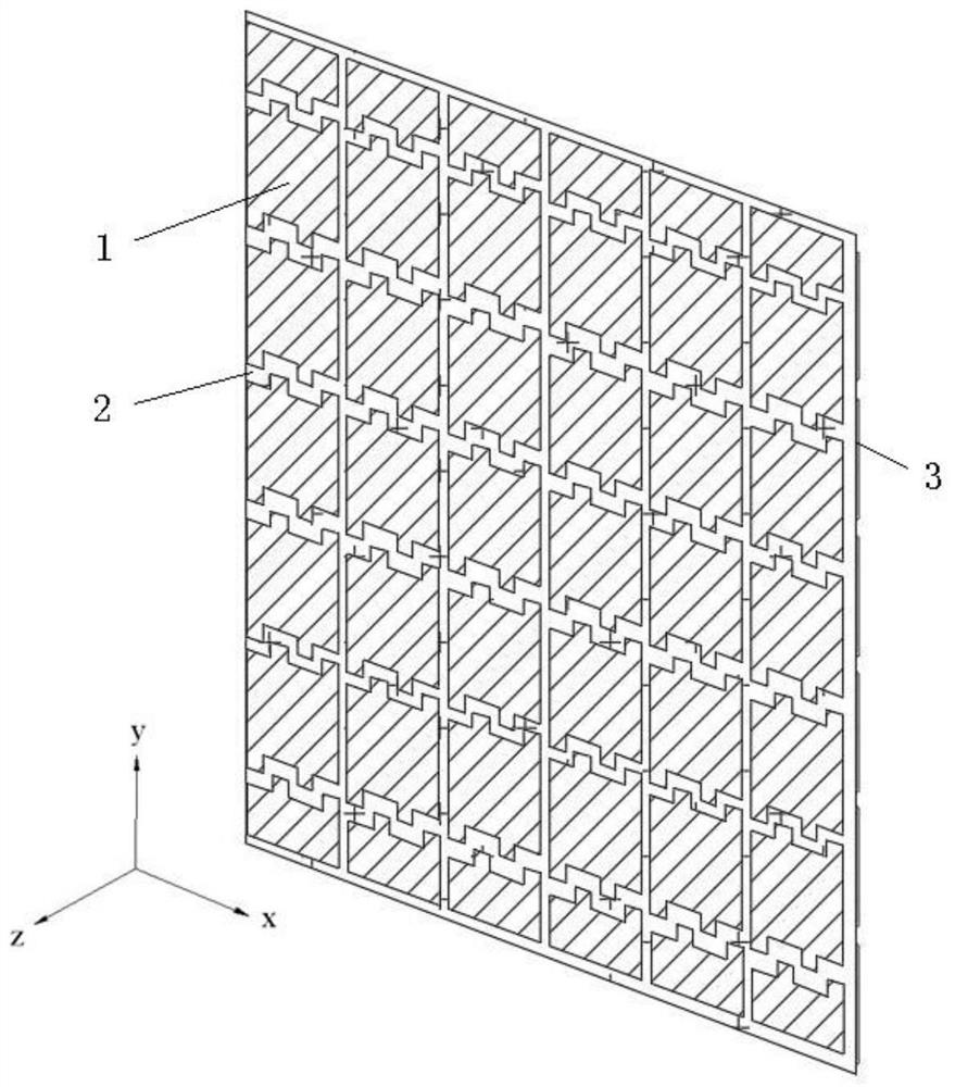
[0045] The task is to simulate a thin dielectric plate with a thickness of 1.5mm and a relative permittivity of 4.4 at 24GHz. Specific embodiments: the material of the first metal coating 1 and the second metal coating 3 of the artificial dielectric of the present invention is copper, and the thickness t of the first metal coating 1 and the second metal coating 3 f Both are 0.018mm; the substrate 2 is made of polyimide flexible CCL sheet, and the thickness of the substrate 2 is t s is 0.0254mm, the relative permittivity is 3.5, and the loss tangent is 0.018; the arrangement period of the interdigitated metal patches is a x =a y =0.9mm, fork finger width w, fork length d, and adjacent fork finger gap g are all 0.15mm, and the number of fork fingers on one side of each fork finger strip metal patch is n d = 3, so the width of the entire interdigitated strip w e =n d *(w+g)-g=0.75mm, the distance s=0.5mm between each fork finger and the adjacent non-belonging fork finger stri...

Embodiment 2

[0047] The task is to simulate a thickness of t d = 3 mm thicker dielectric plate with a relative permittivity of 5.6 at 24 GHz. For thicker dielectric plate simulation tasks, several artificial dielectrics proposed by the present invention can be placed in a certain period a z Arranged to get. In this embodiment, two artificial dielectrics are chosen to be a z =1.5mm is the periodic arrangement along the longitudinal direction to simulate t d = 3mm thick dielectric, the double-layer periodic unit structure of the resulting cascade structure is as follows Figure 9 shown. The configuration of each artificial dielectric in this embodiment is exactly the same, specifically as follows: the material of the first metal coating 1 and the second metal coating 3 is copper, the thickness of the first metal coating 1 and the second metal coating 3 t f Both are 0.018mm; the substrate 2 is made of polyimide flexible CCL sheet, and the thickness of the substrate 2 is t s is 0.0254mm...


PUM

PropertyMeasurementUnit
thicknessaaaaaaaaaa
relative permittivityaaaaaaaaaa

Abstract

An artificial dielectric of the present invention comprises a substrate, a first metal coating attached to one side of the substrate, and a second metal coating attached to the other side of the substrate; the first metal coating consists of Composed of multiple rows of metal patches, each row of metal patches includes multiple metal patches; the second metal cladding layer is composed of multiple columns of metal patches, each column of metal patches includes multiple metal patches; adjacent metal patches There is a gap between the pieces, each metal patch has a plurality of fingers, a depression is formed between two adjacent fingers, and two adjacent metal patches, one of the fingers of the metal patch is connected to the other metal patch The depressions of the patches correspond. The artificial dielectric of the present invention has a wide adjustment range of its equivalent relative permittivity and a high upper limit, which can meet the needs of flexible regulation of electromagnetic waves in existing high-performance applications; its unit resonance frequency is high, which can meet In the higher microwave frequency band, the requirement of higher relative permittivity is realized.

Description

technical field [0001] The invention relates to the field of dielectric technology, in particular to an artificial dielectric. Background technique [0002] Artificial dielectrics are artificial structures with equivalent dielectric properties that are periodically arranged with sub-wavelength artificial structures. In recent years, artificial dielectrics have been widely used in microwave and antenna engineering, such as reducing the size of microwave devices, increasing the directivity of antennas, and realizing antenna beam steering. In the application of lens antennas, artificial dielectrics have obvious advantages in terms of refractive index, impedance, and polarization. For example, in the gradient index (GRIN) metamaterial lens antenna, the square annular artificial dielectric is used to increase the bandwidth and achieve dual polarization; in the IML structure lens antenna, the H-shaped artificial dielectric is used to achieve bandwidth enhancement, beam focusing, ...

Claims


Application Information

Patent Timeline
Patent Type & Authority Patents(China)
IPC IPC(8): H01Q1/38H01Q9/04H01Q9/16H01Q15/08
CPCH01Q1/38H01Q9/0407H01Q9/16H01Q15/08
Inventor 杨歆汨刘倩云朱立宇黄克猛
Owner WUTONG HLDG GRP CO LTD
Why Eureka
Try Eureka