
Machining method for drill bit with blade inclined groove structures for machining composite material

A processing method and composite material technology, which are applied in the field of drilling tools in machining, can solve the problems of difficult to realize fiber composite materials, the inlet fibers of the composite materials cannot play a good cutting effect, and the inlet tear is serious, and reduce the inlet Effect of tear damage, suppression of entrance tear and burr damage, and efficient hole making

Active Publication Date: 2020-02-04
DALIAN UNIV OF TECH
View PDF6 Cites 3 Cited by
  • Summary
  • Abstract
  • Description
  • Claims
  • Application Information

AI Technical Summary

Problems solved by technology

However, this tool cannot cut the fiber at the entrance of the composite material well, and the entrance is severely torn
It can be seen that the existing tools are difficult to achieve low-damage hole making on the entrance of fiber composite materials

Method used


Image

  • Machining method for drill bit with blade inclined groove structures for machining composite material
  • Machining method for drill bit with blade inclined groove structures for machining composite material
  • Machining method for drill bit with blade inclined groove structures for machining composite material

Examples


Embodiment Construction

[0014] The specific implementation manners of the present invention will be described in detail below in conjunction with the drawings and technical solutions.

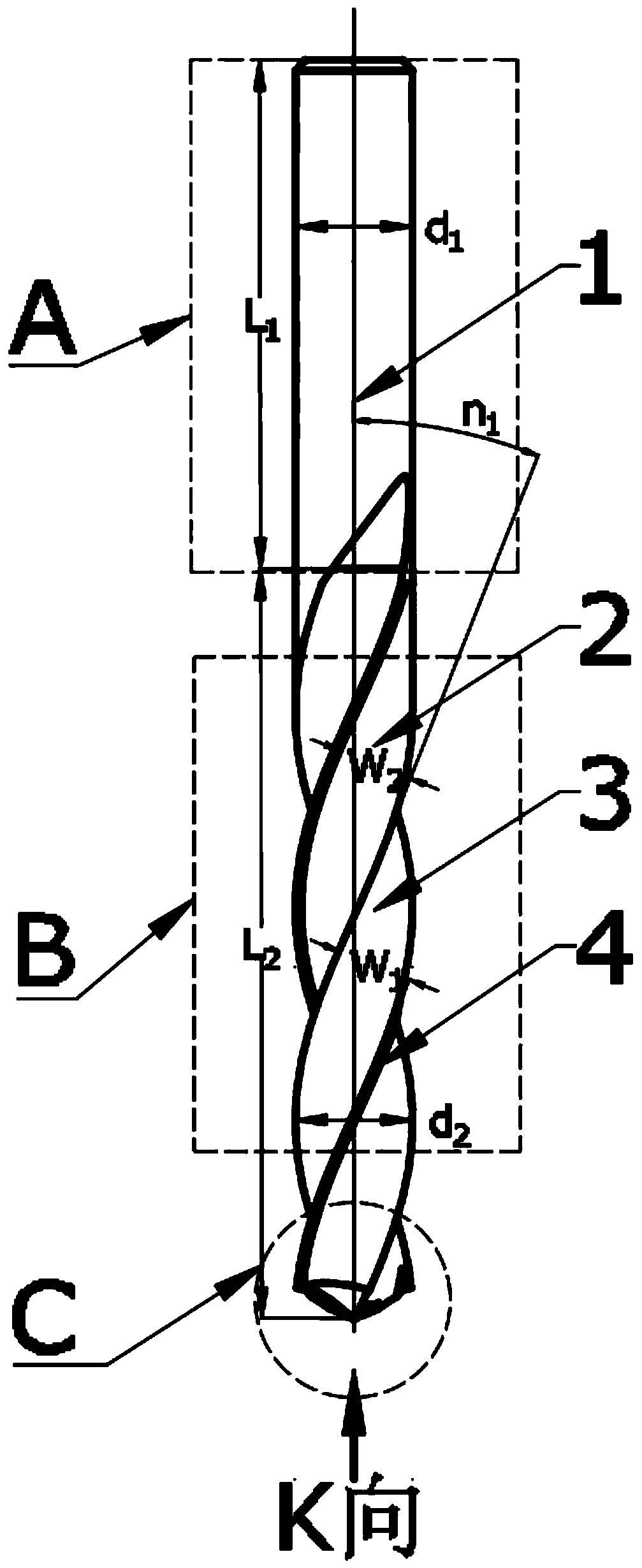
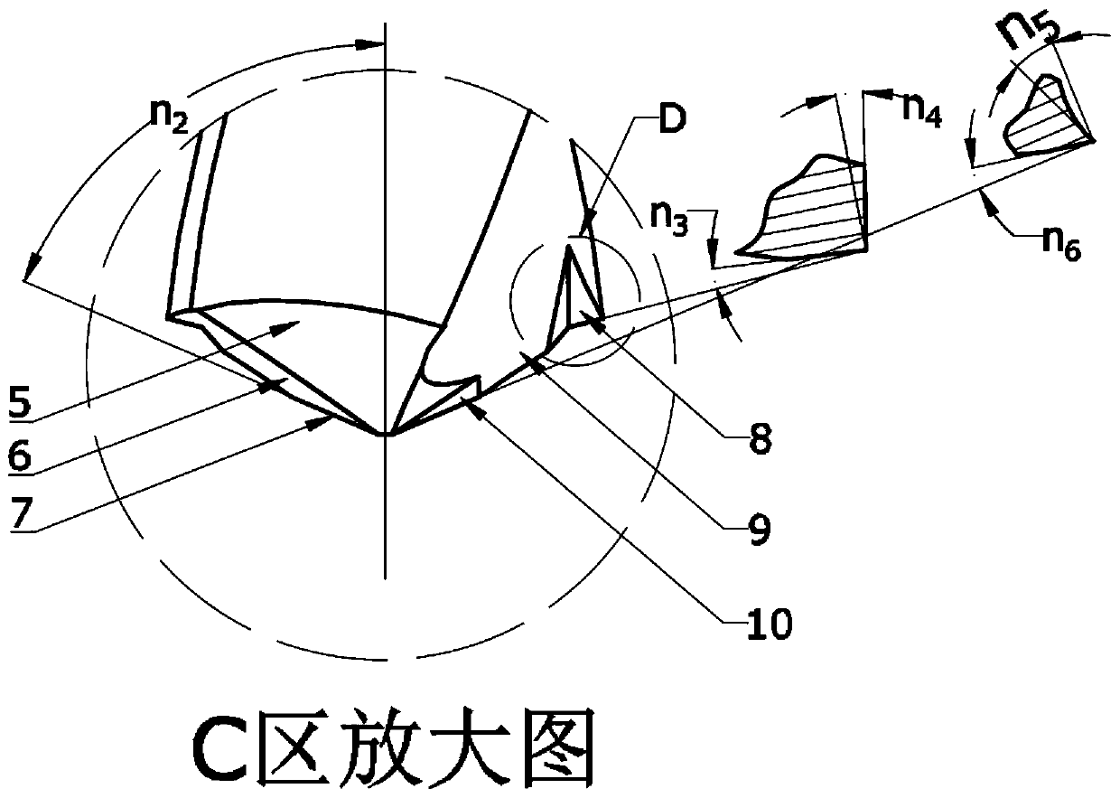
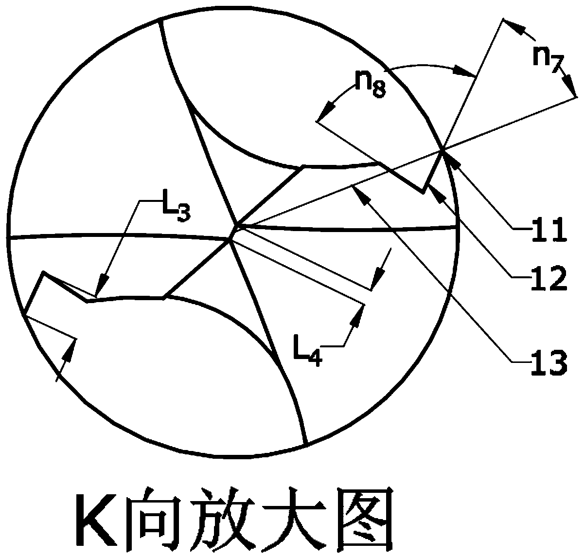
[0015] like figure 1 , figure 2 , image 3 As shown, the drill bit with edge groove structure of the present invention is composed of three parts: the shank area A of the tool clamping part, the minor cutting edge area B of the main body part of the drill bit, and the tool nose area C of the main cutting part of the drill. Generally, the secondary cutting edge area B of the drill has two chip flutes 3 and two edge backs 2, and there are secondary cutting edges 4 on the edge back 2, and the chip flute width W 1 0.8-0.9 times the tool diameter d 2 , blade width W 2 2.5-3.4mm; the angle n formed by the flute 3 and the tool axis 1 1 30°-45°. Tool diameter d 2 and cutting edge length L 2 The length L of the tool holding part can be determined according to the diameter and depth of the drilled hole 1 It can also b...


PUM


Abstract

The invention discloses a machining method for a drill bit with blade inclined groove structures for machining a composite material, belongs to the technical field of drilling tools in machining, andrelates to the machining method for the drill bit with the blade inclined groove structures for machining the composite material. According to the machining method, a downward component force is generated by a front tool face of the drill bit to an inlet material, turning-up of the inlet material is restrained, and the end face blade inclination angle at the outer edge turning point of a tool tiparea of the drill bit is made to be a positive value. In the tool tip area of the drill bit, the front tool face and a rear tool face are partially ground firstly. Then, a grinding wheel is used for grinding the front tool face at the outer edge turning point to obtain the two blade inclined groove structures. After grinding, a new front tool face and a new blade are obtained, and the end face blade inclination angle formed by the new blade and a base face is a positive angle. According to the drill bit with the blade inclined groove structures machined through the method, the current situation that the end face blade inclination angles of traditional drill bits are all negative angles is changed, stripping and layering of fiber materials at the inlet position can be effectively restrained, inlet tearing and burr damage are effectively prevented, and low-damage machining of a hole inlet during composite material drilling is achieved.

Description

technical field [0001] The invention belongs to the technical field of drilling tools in mechanical processing, and relates to a drilling method for processing composite materials with an inclined groove structure. Background technique [0002] Fiber-reinforced composites (FRP) have been widely used in the aerospace field due to their high specific strength and corrosion resistance. In order to realize connection and assembly, it is inevitable to carry out hole-making processing on composite material components, such as positioning pin holes and counterweight holes of composite tail rotor blades of helicopters. However, due to the weak restraint of the surface fibers of composite materials, damage such as burrs and tears occurs frequently when metal drills are used to make holes, especially when drilling entry materials, the surface fibers are easily bent upwards under the action of the main cutting edge , causing the entrance to peel and delaminate, resulting in cracking a...

Claims


Application Information

Patent Timeline
Patent Type & Authority Applications(China)
IPC IPC(8): B23B51/00B27G15/00B28D1/14
CPCB23B51/00B27G15/00B28D1/146B24B3/32
Inventor 王福吉闫建博贾振元赵猛郝佳轩樊俊峰
Owner DALIAN UNIV OF TECH
Learn More