Energy storage system control method and system

A technology of an energy storage system and a control method, applied in the field of renewable energy output control, can solve the problems of low energy storage utilization rate and the like

Active Publication Date: 2020-02-04
SHANDONG UNIV +1
View PDF8 Cites 2 Cited by
  • Summary
  • Abstract
  • Description
  • Claims
  • Application Information

AI Technical Summary

Problems solved by technology

[0005] The present application provides an energy storage system control method and system to solve the problem of low energy storage utilization rate in the energy storage system control method in the prior art

Method used


Image

  • Energy storage system control method and system
  • Energy storage system control method and system
  • Energy storage system control method and system

Examples


Embodiment 1

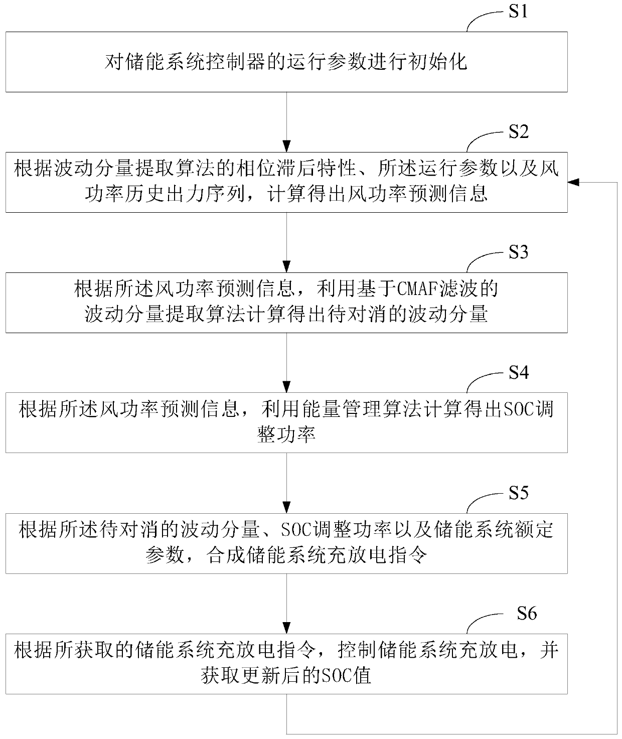
[0073] see figure 1 , figure 1 It is a schematic flowchart of an energy storage system control method provided in the embodiment of the present application. Depend on figure 1 It can be seen that the energy storage system control method in this embodiment mainly includes the following processes:

[0074] S1: Initialize the operating parameters of the energy storage system controller.

[0075] In this embodiment, the initialization of the operating parameters of the energy storage system controller is mainly to set the main parameters of the energy storage system controller and start the control process.

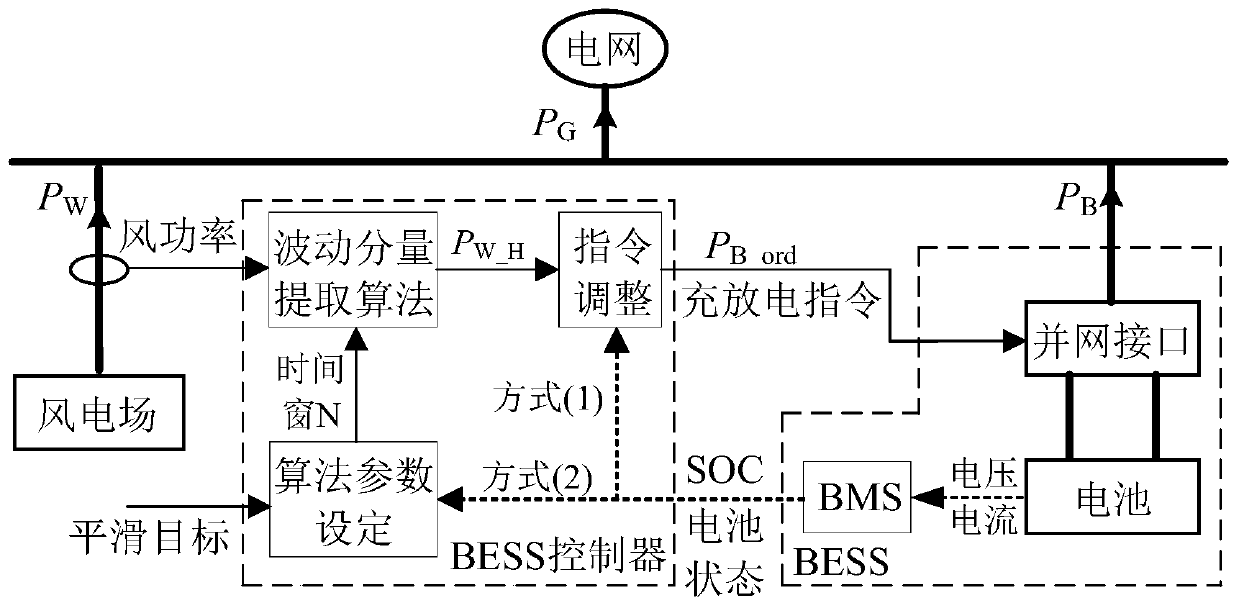
[0076] The energy storage system in this embodiment takes BESS (Battery Energy Storage System, battery energy storage system) as an example. figure 2 It is a schematic diagram of the structure of the wind storage combined system in the embodiment of the present application, that is, the structural composition diagram of a typical wind storage combined power generation sy...

Embodiment 2

[0148] exist Figure 1-Figure 7b On the basis of the illustrated embodiment see Figure 8 , Figure 8 It is a schematic structural diagram of an energy storage system control system provided in the embodiment of this application. Depend on Figure 8 It can be seen that the control system in this embodiment mainly includes: initialization module, wind power prediction information calculation module, fluctuation component calculation module to be canceled, SOC adjustment power calculation module, energy storage system charge and discharge command synthesis module, charge and discharge control module and cycle The module has seven parts. The control system is set inside the energy storage system controller.

[0149] Wherein, the initialization module is used to initialize the operating parameters of the energy storage system controller. The wind power prediction information calculation module is used to calculate the wind power prediction information according to the phase l...


PUM


Abstract

The invention discloses an energy storage system control method and system. The method comprises the steps of initializing operation parameters of an energy storage system controller, calculating windpower prediction information according to the phase lag characteristics, the operation parameters and the historical wind power output sequence of the fluctuation component extraction algorithm, fusing the wind power prediction information into a fluctuation component extraction algorithm based on CMAF filtering to calculate a fluctuation component to be cancelled, fusing the fluctuation component to be cancelled into an energy management algorithm to calculate SOC adjustment power, synthesizing an energy storage system charging and discharging instruction by integrating the fluctuation component and the SOC adjustment power, and controlling the charging and discharging of the energy storage system according to the instruction. The system comprises an initialization module, a wind power prediction information calculation module, a to-be-cancelled fluctuation component calculation module, an SOC adjustment power calculation module, an energy storage system charging and discharging instruction synthesis module, a charging and discharging control module and a circulation module. According to the method, the utilization rate of the energy storage system can be effectively improved, the method is simpler and more visual, the application threshold is lowered, and the application and popularization are facilitated.

Description

technical field [0001] The present application relates to the technical field of renewable energy output control in power grids, in particular to an energy storage system control method and system. Background technique [0002] With the progress of science and technology and the development of economy, the development and utilization of renewable energy has become more and more in-depth, and the grid-connected scale of wind power, photovoltaic and other renewable energy sources has also continued to expand. At the same time, the volatility and randomness of renewable energy power sources have increasingly significant impacts on the safe and stable operation of the power grid and power quality, and have gradually become an important factor restricting the continued expansion of renewable energy power sources. In view of this situation, how to use the energy storage system to smooth the output power fluctuations of renewable energy sources, so as to improve the stability and c...

Claims


Application Information

Patent Timeline
Patent Type & Authority Applications(China)
IPC IPC(8): H02J3/32H02J3/38
CPCH02J3/32Y02E10/76Y02E70/30
Inventor 施啸寒张恒旭赵雅文王晓磊刘洋魏传芝肖天李泽宇石淼岩周博曦
Owner SHANDONG UNIV
Why Eureka
Try Eureka