Disc-like workpiece automatic perforating device for machining

A technology of mechanical processing and drilling devices, which is applied in the direction of driving devices, metal processing machinery parts, feeding devices, etc., can solve problems such as safety accidents, reduce work efficiency, and cumbersome drilling operations, and achieve a high degree of automation and improve work efficiency Effect

Inactive Publication Date: 2020-02-07
赣州靖扬科技有限公司
View PDF5 Cites 22 Cited by
  • Summary
  • Abstract
  • Description
  • Claims
  • Application Information

AI Technical Summary

Problems solved by technology

[0003] During mechanical processing, some disc-shaped workpieces need to be punched. The existing workpiece punching devices are generally manually discharged by the staff, then punched, and then reclaimed. This kind of punching operation is

Method used


Image

  • Disc-like workpiece automatic perforating device for machining
  • Disc-like workpiece automatic perforating device for machining
  • Disc-like workpiece automatic perforating device for machining

Examples


Embodiment 1

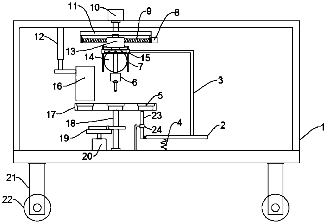
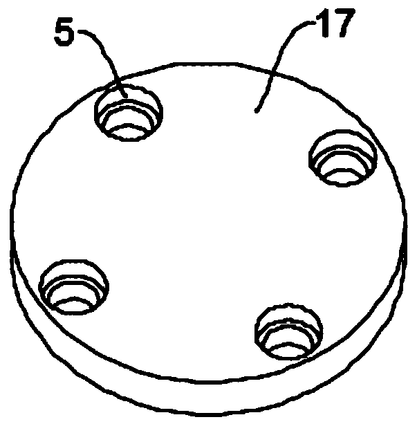
[0025] see Figure 1~2 , in an embodiment of the present invention, an automatic punching device for a disc-shaped workpiece for mechanical processing, comprising a frame 1, a drilling mechanism and a workbench 17, the bottom of the frame 1 is uniformly and symmetrically fixedly equipped with support legs 21, and the support legs 21 bottom end is equipped with roller 22, and described roller 22 is self-locking type roller, and the movement of convenience device, described frame 1 is equipped with workbench 17, and the frame 1 is positioned at the top of workbench 17 and is equipped with drilling mechanism, The workbench 17 is mounted on the frame 1 through the rotating shaft 18. The workbench 17 is provided with a plurality of stepped through holes 5 at equidistant intervals in the circumferential direction. The driving mechanism on which the table 17 rotates intermittently. In this embodiment, the driving mechanism includes a second motor 20 and a sheave mechanism 19. The sec...

Embodiment 2

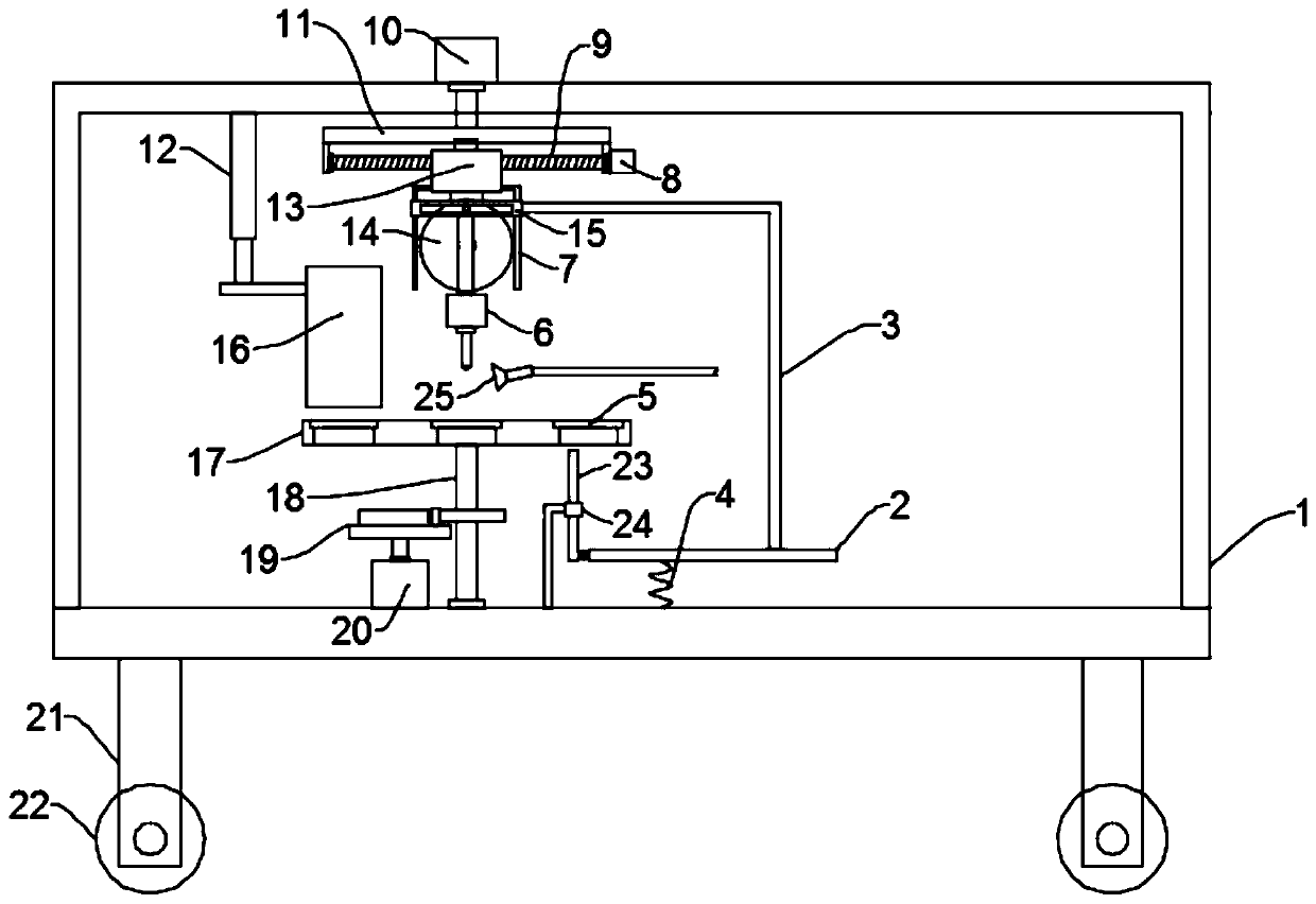
[0028] see image 3 The difference between this embodiment of the present invention and Embodiment 1 is that, further, a nozzle 25 is installed on one side of the processing station above the workbench 17, and the nozzle 25 is connected to the cutting fluid supply pipeline for lubrication and cooling during drilling , Protect the drill bit and the workpiece, and improve the processing efficiency.

[0029] The working principle of the present invention is: when the present invention is in use, the disc-shaped workpiece in the barrel 16 falls into a stepped hole on the workbench 17, and then the driving mechanism drives the workbench 17 to rotate so that the disc-shaped workpiece is located below the drilling mechanism After stopping, the power mechanism drives the drilling assembly 6 to move downward to drill holes. After the drilling is completed, the power mechanism drives the drilling assembly 6 to move upward, and then the workbench 17 rotates again, and the disc-shaped wor...


PUM


Abstract

The invention discloses a disc-like workpiece automatic perforating device for machining. The disc-like workpiece automatic perforating device comprises a machine frame, a drilling mechanism and a workbench; the machine frame is provided with the workbench; the position, located above the workbench, of the machine frame is provided with the drilling mechanism; the position, located on one side ofa rotary shaft, of the machine frame is provided with a driving mechanism which is used for driving the rotary shaft and the workbench on the machine frame to intermittently rotate; the drilling mechanism comprises a drilling assembly and a power mechanism which is used for driving the drilling assembly to ascend and descend; an ejector rod is arranged at a discharging station located under the workbench; and an adjusting mechanism is connected between the drilling assembly and the machine frame and comprises a stepping motor, an installation plate, a screw rod, a first motor and a moving block. The disc-like workpiece automatic perforating device is provided with the drilling mechanism, the driving mechanism and the ejector rod, feeding, drilling and discharging can be automatically conducted, the automation degree is high, and the working efficiency is improved; and an electric push rod is arranged, the adjusting mechanism is arranged, the drilling position can be adjusted, and different machining requirements are met.

Description

technical field [0001] The invention relates to the technical field of mechanical processing, in particular to an automatic punching device for a disc-shaped workpiece for mechanical processing. Background technique [0002] Machining refers to the process of changing the shape or performance of a workpiece through a mechanical device. According to the difference in processing method, it can be divided into cutting processing and pressure processing. [0003] During mechanical processing, some disc-shaped workpieces need to be punched. The existing workpiece punching devices are generally manually discharged by the staff, then punched, and then reclaimed. This kind of punching operation is more convenient. It is cumbersome, and the punching speed is slow and the efficiency is low, which reduces the work efficiency to a certain extent. On the other hand, because the staff operates more, then it is easy to cause safety accidents. Contents of the invention [0004] The obje...

Claims


Application Information

Patent Timeline
IPC IPC(8): B23B41/00B23B47/00B23B47/20B23B47/18B23Q5/40B23Q7/00B23Q7/02B23Q7/14B23Q11/10
CPCB23B41/00B23B47/00B23Q5/10B23Q5/40B23Q7/006B23Q7/02B23Q7/14B23Q11/10
Inventor 徐海东
Owner 赣州靖扬科技有限公司
Why Eureka
Try Eureka