Unmanned aerial vehicle device for power transmission tower image recognition
A power transmission tower, image recognition technology, applied in the direction of circuit devices, battery circuit devices, transportation and packaging, etc., can solve the problems of inconvenient UAV balance force, difficult UAV control balance, etc., to achieve functional scalability, high performance Reliable, adaptable results
- Summary
- Abstract
- Description
- Claims
- Application Information
AI Technical Summary
Problems solved by technology
Method used
Image

Examples
Embodiment 1
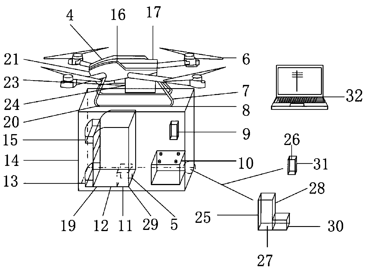
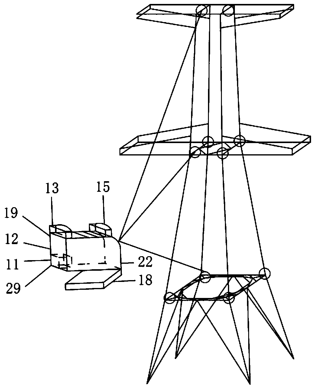
[0024] Embodiment 1: as Figure 1-Figure 5 As shown, it includes UAV flight wing 6, UAV connection frame 7, connection chute 8, main signal wake-up device 9, scanner installation chassis 12, thermal imaging camera 13, chassis 14, laser scanner 15, no Man-machine main frame 17, scanner fixed frame 19, visual camera 21, iron tower fixed scanner 22, distance measuring device 23 and GPS device 24, unmanned aerial vehicle flying wing 6 is installed on the unmanned aerial vehicle main frame 17, unmanned The main frame 17 is fixedly connected to the connection chute 8 on the upper surface of the chassis 14 through the UAV connecting frame 7, and the infrared thermal imager 13 and the laser scanner 15 are installed on the scanner installation chassis 12, and the scanner installation chassis 12 Fixedly connected on the scanner fixed frame 19, the scanner fixed frame 19 is fixed on the left front of the cabinet 14 to prevent the scanner from being installed in the cabinet 12. For the i...
Embodiment 2
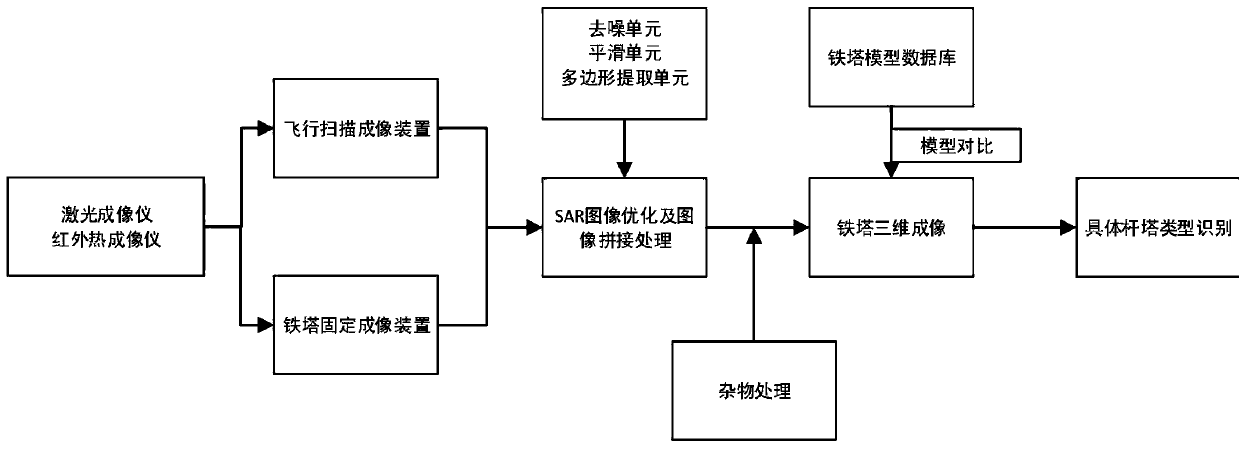
[0028] Embodiment 2: as Figure 1-Figure 5 As shown, a power transmission tower image recognition system includes an image acquisition system 1 and a control system 2, the image acquisition system 1 includes a flight device 4 and an image acquisition device 5 installed on the flight device 4, and the control system 2 is used to control unmanned The flight device 4 provides power for ascent and flight to ensure that the system can collect each rod of the iron tower. The image acquisition device 5 is used for image acquisition and three-dimensional imaging of the power transmission tower.
[0029] Preferably, the above-mentioned image acquisition system 1 includes a UAV flight wing 6, a UAV connection frame 7, a connection chute 8, a main signal wake-up device 9, a scanner installation chassis 12, an infrared thermal imager 13, a chassis 14, a laser Scanner 15, UAV main frame 17, scanner fixed frame 19, visual camera 21, iron tower fixed scanner 22, distance measuring device 23 ...
Embodiment 3
[0037] Embodiment 3: An optimization method for a power transmission tower image recognition system, taking the JD11 power transmission tower with a height of 24m as an example, using Figure 1-5 Briefly describe the image recognition and optimization system of the transmission tower. The image recognition and optimization system of the transmission tower includes the image acquisition system 1, the control system 2, and the tower model optimization system. This system is used for image acquisition and optimization:
[0038] The UAV flight wing 6 is installed on the UAV main frame 17, and the UAV main frame 17 is connected with the chassis 14 at the connection chute 8 through the UAV connection frame 7, and the UAV connection frame 7 is connected The screw 20 is opened, allowing the bottom of the UAV connection frame 7 to pass through the connection chute 8 and then fix the screw 20. The thermal imager 13 and the laser scanner 15 are installed on the scanner installation case ...
PUM
 Abstract
Description
Claims
Application Information